

Search


EMF Equation of a Transformer

Explore the step-by-step derivation of the transformer EMF equation using sinusoidal flux. Understand flux linkage, turn ratio, and the role of core flux density in voltage generation.

Edwiin
Field: Power switch
10Year<
China
Add us on Google

Background of Transformer EMF Equation Derivation

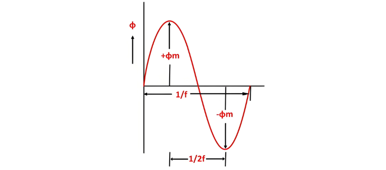
When a sinusoidal voltage is applied to the transformer's primary winding, an alternating flux ϕm is induced in the iron core. This sinusoidal flux links both primary and secondary windings, with its functional form described by a sine function.

Mathematical Derivation of Flux Rate of Change

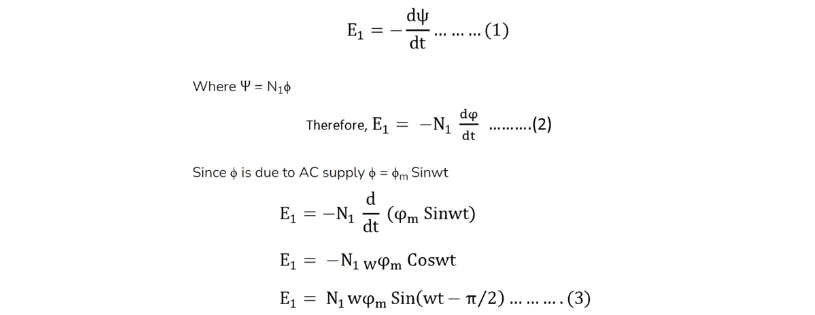
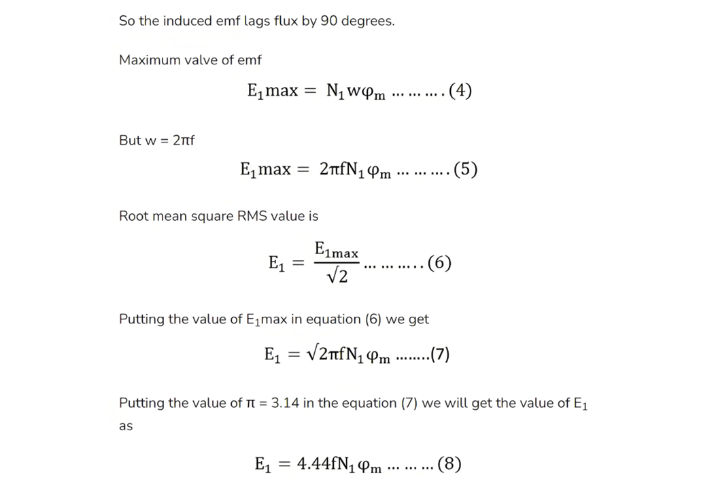
The following outlines the derivation of the transformer's EMF equation, with defined parameters:

  • ϕm: Maximum flux (Weber)

  • f: Supply frequency (Hz)

  • N1: Number of primary turns

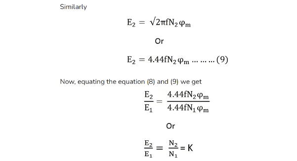
  • N2: Number of secondary turns

  • &Phi;: Flux per turn (Weber)

EMF Equation of a Transformer

EMF Equation of a Transformer

EMF Equation of a Transformer

EMF Equation of a Transformer

Turn Ratio and Flux Density Relation

The above equation is referred to as the turn ratio, where K denotes the transformation ratio.

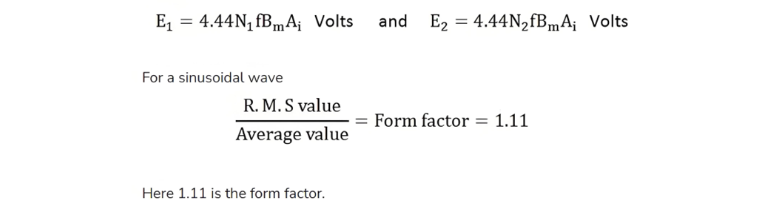
Using the relation ϕm=Bm&times;Ai (where Ai is the iron core cross-sectional area and Bm is the maximum flux density), Equations (8) and (9) can also be expressed as:

EMF Equation of a Transformer

Give a tip and encourage the author!

Comments

Share your question or perspective
WhatsApp
Send inquiry
+86
Click to upload file
Download
Get the IEE Business Application
Use the IEE-Business app to find equipment, obtain solutions, connect with experts, and participate in industry collaboration anytime, anywhere—fully supporting the development of your power projects and business.
Login
or continue with
New here?
Register








