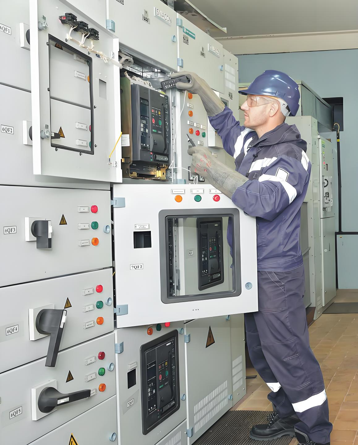
Maayong praktis sa pagoperahan sa switchgear circuit breakers ug contactors
Pagoperahan sa LV/MV
Switchgear
Ang layo niining gidakel mao ang maghatag og rekomendadong praktis alang sa pagoperahan ug inspeksyon sa medium - voltage (2 - 13.8 kV) ug low - voltage (200 - 480 V) draw - out switchgear circuit breakers ug contactors. Ang maayo nga reguladong operasyon labi ka importante aron mapadako ang performance ug serbisyo sa planta equipment, sama sa pagseguro isip usa ka safe working environment para sa plant personnel.

Nahatagan kini nga artikulo sa responsibilidad sa operating personnel, kasama ang ilang daily checks ug inspeksyon sa switchgear. Kasagaran, ihatag usab nito ang optimal nga praktis alang sa pagoperahan ug proteksyon sa transformers, motors, buses, cables, circuit breakers, ug contactors.
Ang tungod sa operating personnel mao ang magsetup ug gamiton regular routine inspections sa tanang switchgear sa planta. Ang circuit breakers, contactors, ug busbars dapat mahimong clean ug dry aron mapalitog ang panganak nganong insulation failures nga mahimo mog resulta sa explosions ug fires. Kasagaran, mas maayo nga giinspeksyon kada adlaw.
Ania ang mga rekomendadong daily inspection items alang sa switchgear:
Kon naa ania nga anomaly nakit-an sa ingani nga proseso sa inspeksyon, maintenance work orders dapat iissue.
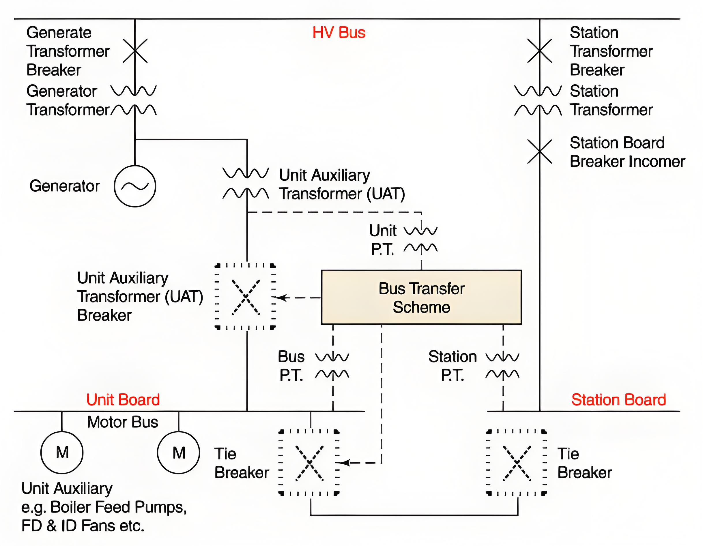
Ihatag kini sa practices for load feeder overcurrent ug ground fault protection, kasama ang source ug tie overcurrent protection, ug uban pang crucial practices related sa transformers. Padayon, i-address kini sa switchgear bus transfers ug explore ang issues nga mosulob sa paralleling of two power sources ug sa switch - time transfer schemes.
Proteksyon
Ang protective relays coordinated such that only those circuit breakers o contactors nga kinahanglan nga mog operate aron isolate faults trip open automatic. Kini enables the maximum number of equipment to stay in operation, minimizing the impact on on - line generating units. It also gives an indication of the location of the electrical fault.
Electrical faults sa transformers, motors, busbars, cables, circuit breakers, ug contactors typical nga permanent. Bago re - energize ang equipment, thorough investigation of the operation of protective relays must be carried out.
The magnitude of electrical short - circuit currents usually ranges from 15,000 to 45,000 amperes, depending on the size and impedance of the source transformer.
Load Feeder Ground Protection
Designs nga limit the ground fault current (usually around 1000 amps) apply separate ground relays nga will actuate for ground faults only. These relays trip with very short time delays to isolate the grounded feeders before source or tie circuit breaker ground relays can operate.
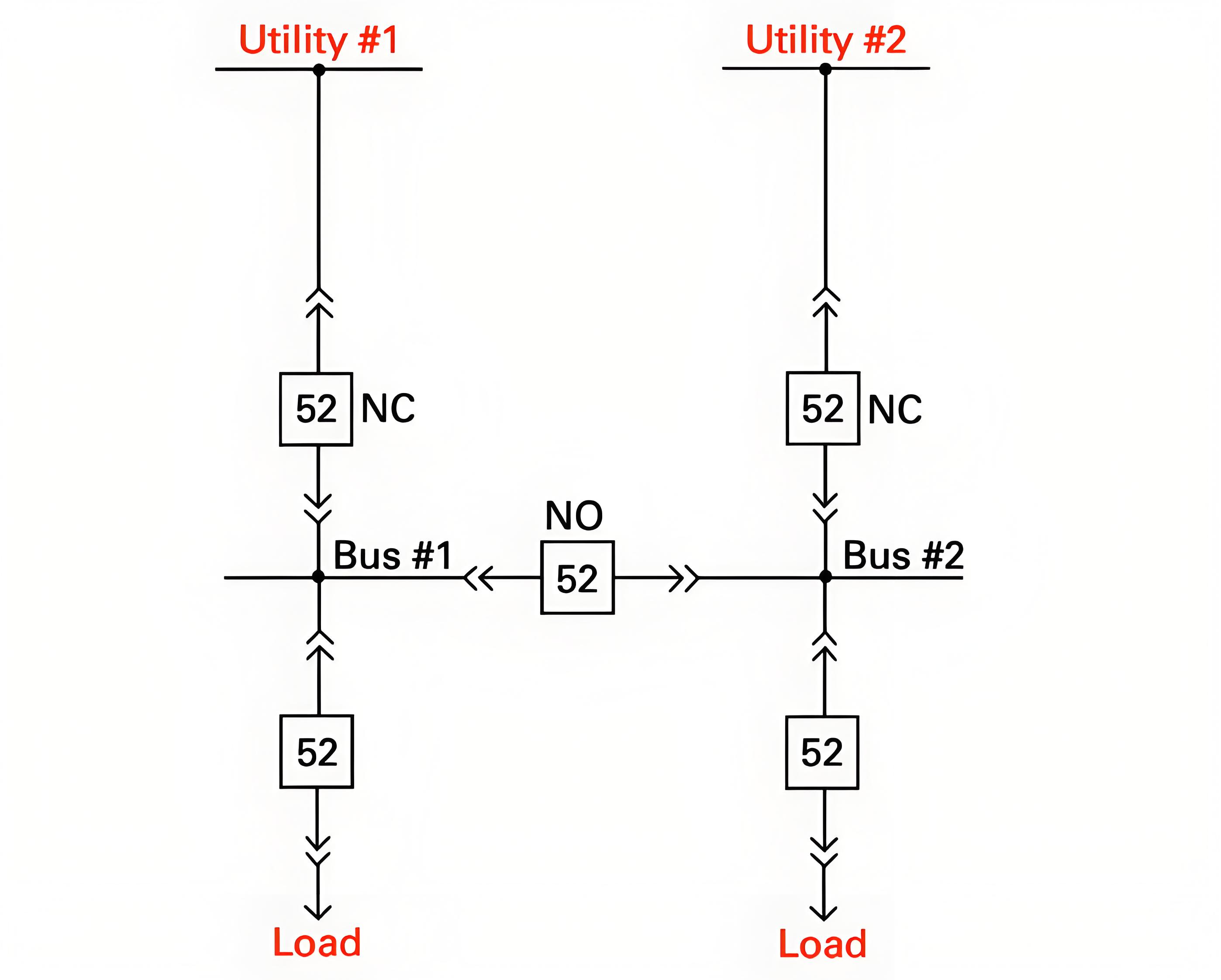
Source and Tie Overcurrent Protection
Source breakers and tie breakers are not equipped with instantaneous tripping elements. Instead, they rely on time delays to coordinate fault responses with downstream buses and loads.
Typically, these relays are set based on the maximum three - phase short - circuit current levels, with an operating time ranging from 0.4 to 0.8 seconds.
Normally, these relays feature an inverse - time characteristic. That is, lower current levels will result in proportionally longer time delays for all relays. Specifically, the tie breaker connected to another bus is set to operate in approximately 0.4 seconds, while the low - side breaker of the source transformer is set to operate in around 0.8 seconds.

High Side Source Transformer Overcurrent Protection
The overcurrent relays on the high - voltage side of the source transformer are typically set to operate approximately 1.2 seconds after a maximum three - phase short - circuit occurs on the low - voltage side. This time delay allows for proper coordination with the overcurrent relays on the low - voltage or secondary side.
These relays generally have an inverse - time characteristic, meaning that lower current levels result in longer operating times. The high - voltage - side overcurrent relays of the source transformer assume that a fault may occur in the transformer itself, in the low - voltage - side connecting buses or cables, or in the low - voltage circuit breaker. They will trip all necessary equipment to isolate the fault.
For Unitized Automatic Transfer Switches (UATs), which are usually equipped with differential protection, the high - voltage - side overcurrent relays can also cause the unit and the main step - up transformer to trip completely. Additionally, if the low - voltage - side breaker fails to interrupt a fault, the high - voltage - side overcurrent relays provide breaker - sticking protection.
Source and Tie Residual Ground Protection
For designs that limit the ground - fault current (usually around 1000 amps), separate ground relays are used, which actuate only in the event of a ground fault. The ground relays of source and tie breakers are not equipped with instantaneous tripping elements. Instead, they rely on time delays to coordinate fault responses with downstream buses and loads. Typically, these relays are set based on the maximum ground - fault current levels, with an operating time ranging from 0.7 to 1.1 seconds.
Normally, these relays exhibit an inverse - time characteristic. That is, lower current levels result in proportionally longer time delays for all relays. Specifically, the tie breaker connected to another bus is set to operate in approximately 0.7 seconds for 100% ground faults, while the low - side breaker of the source transformer is set to operate in around 1.1 seconds.
Source Transformer Neutral Ground Protection
In design schemes aimed at limiting the ground - fault current (usually around 1000 amps), dedicated ground relays are employed. These relays are specifically designed to accurately sense the ground current flowing through the neutral point of the transformer. They are highly targeted and will only be triggered when a ground fault occurs.
Normally, the source transformer neutral - ground relay is set to operate approximately 1.5 seconds after the most severe ground fault occurs. This time - delay setting is crucial as it ensures that the relay can coordinate well with the ground relays of the source breakers and tie breakers.
The neutral - ground relay has a crucial mission. Its core function is to isolate ground faults that occur on the low - voltage side (i.e., the secondary side) of the source transformer. Potential fault locations include the low - voltage windings of the transformer, low - voltage circuit breakers, and the buses and cables connecting them. More importantly, it also serves as a backup protection. In case the low - side breaker fails to function properly when facing a ground fault, the neutral - ground relay will promptly step in to cut off the faulty circuit, thereby ensuring the safe and stable operation of the power system.
Alarm - Only Ground Schemes
Alarm - only ground schemes restrict the ground - fault current to just a few amperes. Typical values are 1.1 amperes for 480 - volt systems and 3.4 amperes for 4 kV systems. For wye - connected source transformers, the neutral point is usually grounded via a grounding transformer. For delta - connected source transformers, the ground - fault current is typically supplied by three transformers, which are connected in a grounded wye configuration on the primary side and an open - delta configuration on the secondary side.
In both scenarios, voltage relays are installed on the secondary sides of the grounding transformers to alert for ground - fault conditions. In the case of delta - connected source transformers, blown primary fuses of the ground - detector transformers can also trigger an alarm.
Both relay schemes issue alarms (usually with a sensitivity of 10% or higher) for all grounded equipment within a specific electrical system. This includes the low - voltage or secondary windings of the source transformer, as well as all connected buses, cables, circuit breakers, potential transformers, and loads.
Switchgear Bus Transfers
Paralleling Two Sources
Paralleling two different power sources is the preferred approach for switching from one source to another. This method imposes no stress on motors, ensures a smooth transition, and poses no threat to the running equipment. However, in many designs, the short - circuit current generated during the paralleling process exceeds the interrupting capacity of feeder breakers.
Source breakers and tie breakers remain unaffected, but feeder breakers may fail to clear close - in faults and could even be damaged in the process. Therefore, the duration of paralleling should be minimized (around a few seconds) to reduce the exposure time and the probability of feeder faults.
Typically, this issue is more pronounced when a generating unit supplies power to one system while the standby or startup transformer is fed from a different system. Reducing the power output of the generator usually brings the phase angles closer together, as the generator's power angle decreases with the reduced load.
Drop - Pickup Transfers
Drop - pickup transfers, also known as switch - time transfer schemes, can potentially damage motors. If the new source breaker fails to close after the previous source breaker trips open, it may cause a running unit to shut down or an operating process to be interrupted. When a busbar loses power, the connected motors act as generators and supply a residual voltage to the busbar.
This residual voltage typically decays within about one second.
However, drop - pickup transfers occur much faster than one second, and the residual voltage can combine with the voltage from the new source. If the vector sum of these two voltages exceeds 133% of the motor's rated voltage, the transfer can reduce the service life of the motors involved.
Automatic Bus Transfer Schemes
Automatic bus transfer schemes are generally designed to mitigate the stress on motors during transfer and to coordinate with fault relays. Coordination with over - current relaying is accomplished by initiating the transfer after the source circuit breaker trips open. If over - current relays cause the source breaker to trip (indicating a bus fault), the automatic transfer will be blocked.
Moreover, these schemes typically employ residual voltage relays and/or high - speed synchronizing check relays. Transfers are only permitted when the vector sum of the residual voltage and the voltage from the new source is less than 133% of the motor's rated voltage. If the transfer is blocked by 86 lockout relays, the scheme usually times out.
However, if this is not the case, operators should verify that the automatic transfer scheme is deactivated before resetting the bus 86 lockout relays.