Kyaukake da na dace-dace don tashar gagarin kasa da kafin kasa
Amfaniyar LV/MV
Tashar Gagarin Kasa
Aikatako wani bayanin da ya haɗa shi shine ya bayyana masu amfaniya da tushen tashar gagarin kasa da kafin kasa mai yawa (2 - 13.8 kV) da kuma mai yawan (200 - 480 V). Amfaniya da tsari shine mafi kyau don yanayi aiki da ma'adani na kayayyakin mulkin, kuma don bincike tsaro da ake da a cikin mulki.

Wannan bayanin ya bayyana abubuwa na masu amfaniya, da kuma binciken da za su yi a tashar gagarin kasa. Amsa, zai bayyana hanyoyi da dama don amfani da tushen da kuma cin kofin transformers, motors, buses, cables, circuit breakers, da kafin kasa.
Shi ne da masu amfaniya bayanin binciken da za su yi a tashar gagarin kasa cikin mulki. Circuit breakers, contactors, da busbars ya kamata zuwa a kan kusa da ciwo don iya rage da sauka da zai iya jan faruwarsa ko jirgin lafiya. Yanzu, ana fi sani da ake yi binciken kowace ranar.
Hadi suna da abubuwan da za su yi a binciken kowace ranar:
Idan akwai wani abu da ba a ciki a nan da aka bayyana, ake rubuta work orders don maintenance.
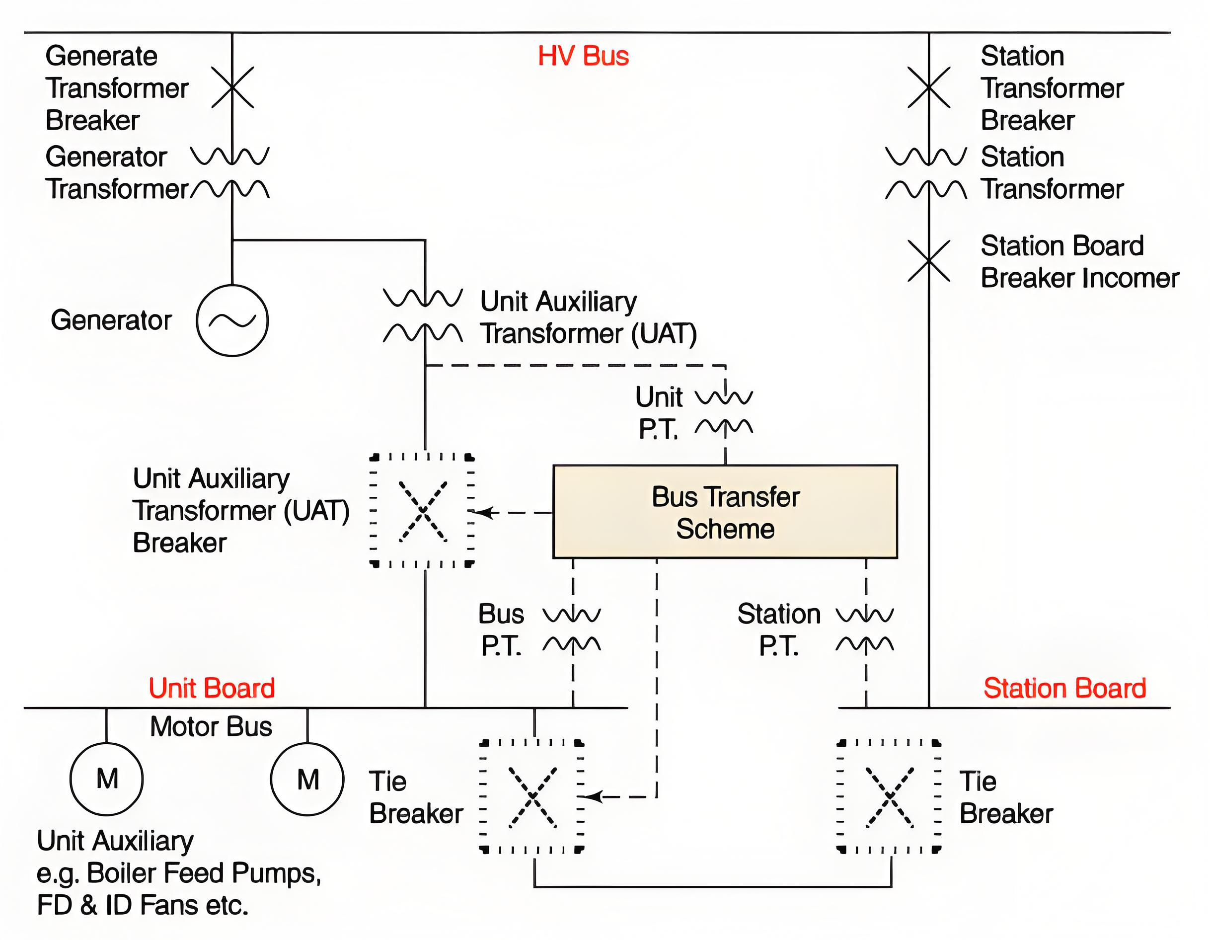
Zai bayyana hanyoyi don overcurrent da ground fault protection na load feeders, da kuma overcurrent protection na source da tie, da wasu abubuwan da dama da transformers. Zai bayyana tushen transfer na tashar gagarin kasa da kuma abubuwan da za su faruwa a lokacin da ake sama duwatsu power sources da kuma switch-time transfer schemes.

Cin Kofi
Protective relays suna tattara saboda haka za mu yi aiki waɗanda suka buƙata don kawo fault. Wannan ya taimaka masu amfaniya don kawo fault, kuma ya rage da dalilin fault.
Faults na transformers, motors, busbars, cables, circuit breakers, da kafin kasa suna ɗaukan da suka faru. Idan akwai wani fault, ya kamata ake yi bincika daidai cewa protective relays suna yi aiki daidai idan akwai wani fault.
Yadda electrical short-circuit currents ke cutar daidai suna ɗaukar da 15,000 zuwa 45,000 amperes, tare da size da impedance na source transformer.
Load Feeder Ground Protection
Designs na ground fault current (da suke da 1000 amps) suna amfani da ground relays mai farko da za su buƙata don ground faults kawai. Wannan relays suna buƙata da time delays kadan-kadan don kawo grounded feeders idan akwai wani fault.
Source and Tie Overcurrent Protection
Source breakers da tie breakers ba suke da instantaneous tripping elements. Hakan, suke da amfani da time delays don tattauna fault responses da downstream buses da loads.
Duk da cewa, wannan relays suna tattara saboda haka da maximum three-phase short-circuit current levels, da operating time da ke ɗaukar da 0.4 zuwa 0.8 seconds.
Yanzu, wannan relays suna da inverse-time characteristic. Yana nufin haka cewa lower current levels suna rage da time delays da kullum. Specifically, tie breaker connected to another bus is set to operate in approximately 0.4 seconds, while the low-side breaker of the source transformer is set to operate in around 0.8 seconds.

High Side Source Transformer Overcurrent Protection
Overcurrent relays na high-voltage side na source transformer suna tattara saboda haka za mu yi aiki kadan-kadan 1.2 seconds bayan da maximum three-phase short-circuit occurs on the low-voltage side. Wannan time delay tana taimaka don tattauna da overcurrent relays na low-voltage or secondary side.
Wannan relays suna da inverse-time characteristic, yana nufin haka cewa lower current levels suna rage da time delays. High-voltage-side overcurrent relays na source transformer suna tattara saboda haka za mu yi aiki kadan-kadan 1.2 seconds bayan da maximum three-phase short-circuit occurs on the low-voltage side. Wannan time delay tana taimaka don tattauna da overcurrent relays na low-voltage or secondary side.
For Unitized Automatic Transfer Switches (UATs), which are usually equipped with differential protection, the high-voltage-side overcurrent relays can also cause the unit and the main step-up transformer to trip completely. Additionally, if the low-voltage-side breaker fails to interrupt a fault, the high-voltage-side overcurrent relays provide breaker-sticking protection.
Source and Tie Residual Ground Protection
For designs that limit the ground-fault current (usually around 1000 amps), separate ground relays are used, which actuate only in the event of a ground fault. The ground relays of source and tie breakers are not equipped with instantaneous tripping elements. Instead, they rely on time delays to coordinate fault responses with downstream buses and loads. Typically, these relays are set based on the maximum ground-fault current levels, with an operating time ranging from 0.7 to 1.1 seconds.
Normally, these relays exhibit an inverse-time characteristic. That is, lower current levels result in proportionally longer time delays for all relays. Specifically, the tie breaker connected to another bus is set to operate in approximately 0.7 seconds for 100% ground faults, while the low-side breaker of the source transformer is set to operate in around 1.1 seconds.
Source Transformer Neutral Ground Protection
In design schemes aimed at limiting the ground-fault current (usually around 1000 amps), dedicated ground relays are employed. These relays are specifically designed to accurately sense the ground current flowing through the neutral point of the transformer. They are highly targeted and will only be triggered when a ground fault occurs.
Normally, the source transformer neutral-ground relay is set to operate approximately 1.5 seconds after the most severe ground fault occurs. This time-delay setting is crucial as it ensures that the relay can coordinate well with the ground relays of the source breakers and tie breakers.
The neutral-ground relay has a crucial mission. Its core function is to isolate ground faults that occur on the low-voltage side (i.e., the secondary side) of the source transformer. Potential fault locations include the low-voltage windings of the transformer, low-voltage circuit breakers, and the buses and cables connecting them. More importantly, it also serves as a backup protection. In case the low-side breaker fails to function properly when facing a ground fault, the neutral-ground relay will promptly step in to cut off the faulty circuit, thereby ensuring the safe and stable operation of the power system.
Alarm-Only Ground Schemes
Alarm-only ground schemes restrict the ground-fault current to just a few amperes. Typical values are 1.1 amperes for 480-volt systems and 3.4 amperes for 4 kV systems. For wye-connected source transformers, the neutral point is usually grounded via a grounding transformer. For delta-connected source transformers, the ground-fault current is typically supplied by three transformers, which are connected in a grounded wye configuration on the primary side and an open-delta configuration on the secondary side.
In both scenarios, voltage relays are installed on the secondary sides of the grounding transformers to alert for ground-fault conditions. In the case of delta-connected source transformers, blown primary fuses of the ground-detector transformers can also trigger an alarm.
Both relay schemes issue alarms (usually with a sensitivity of 10% or higher) for all grounded equipment within a specific electrical system. This includes the low-voltage or secondary windings of the source transformer, as well as all connected buses, cables, circuit breakers, potential transformers, and loads.
Switchgear Bus Transfers
Paralleling Two Sources
Paralleling two different power sources is the preferred approach for switching from one source to another. This method imposes no stress on motors, ensures a smooth transition, and poses no threat to the running equipment. However, in many designs, the short-circuit current generated during the paralleling process exceeds the interrupting capacity of feeder breakers.
Source breakers and tie breakers remain unaffected, but feeder breakers may fail to clear close-in faults and could even be damaged in the process. Therefore, the duration of paralleling should be minimized (around a few seconds) to reduce the exposure time and the probability of feeder faults.
Typically, this issue is more pronounced when a generating unit supplies power to one system while the standby or startup transformer is fed from a different system. Reducing the power output of the generator usually brings the phase angles closer together, as the generator's power angle decreases with the reduced load.
Drop-Pickup Transfers
Drop-pickup transfers, also known as switch-time transfer schemes, can potentially damage motors. If the new source breaker fails to close after the previous source breaker trips open, it may cause a running unit to shut down or an operating process to be interrupted. When a busbar loses power, the connected motors act as generators and supply a residual voltage to the busbar.
This residual voltage typically decays within about one second.
However, drop-pickup transfers occur much faster than one second, and the residual voltage can combine with the voltage from the new source. If the vector sum of these two voltages exceeds 133% of the motor's rated voltage, the transfer can reduce the service life of the motors involved.
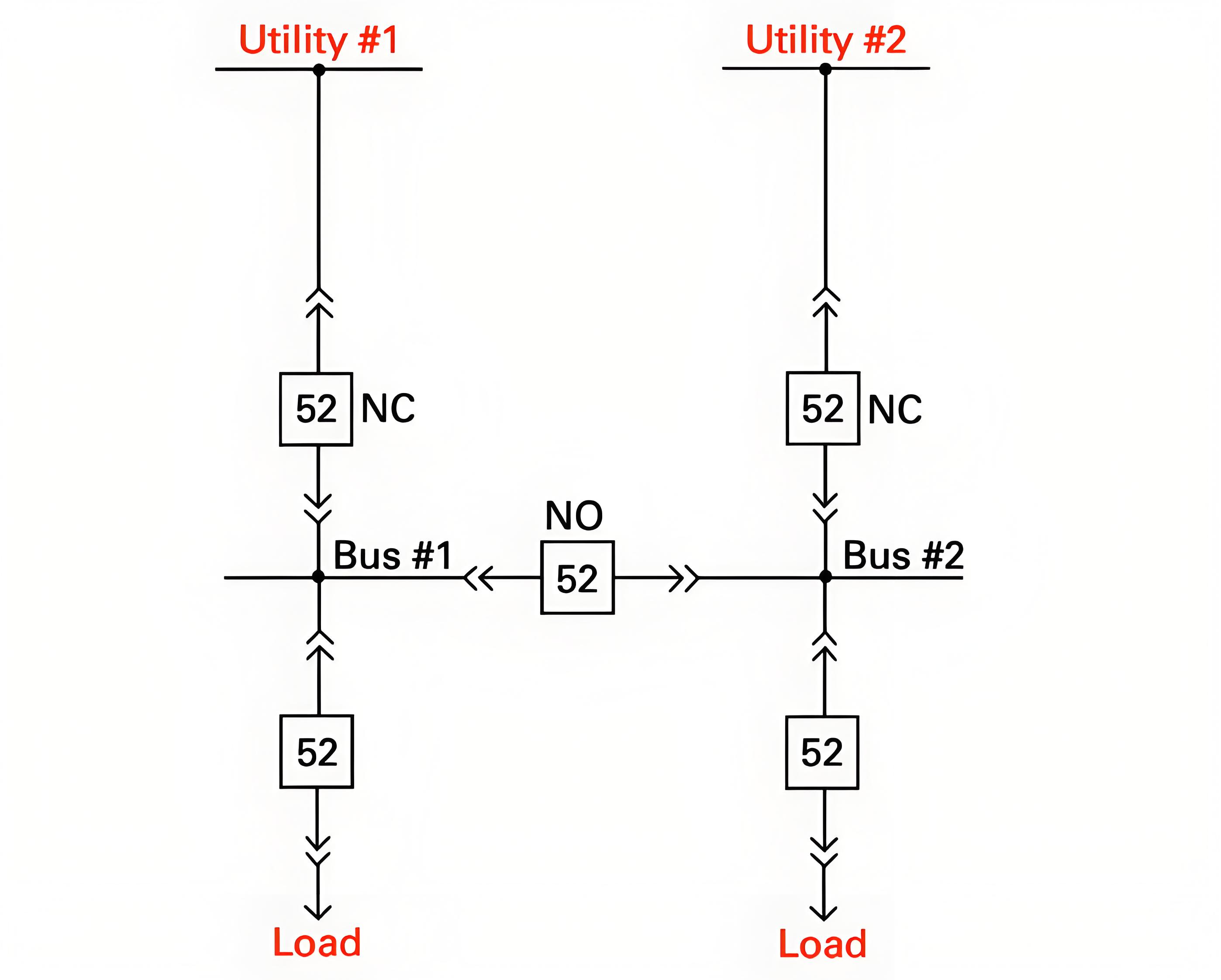
Automatic Bus Transfer Schemes
Automatic bus transfer schemes are generally designed to mitigate the stress on motors during transfer and to coordinate with fault relays. Coordination with over-current relaying is accomplished by initiating the transfer after the source circuit breaker trips open. If over-current relays cause the source breaker to trip (indicating a bus fault), the automatic transfer will be blocked.
Moreover, these schemes typically employ residual voltage relays and/or high-speed synchronizing check relays. Transfers are only permitted when the vector sum of the residual voltage and the voltage from the new source is less than 133% of the motor's rated voltage. If the transfer is blocked by 86 lockout relays, the scheme usually times out.
However, if this is not the case, operators should verify that the automatic transfer scheme is deactivated before resetting the bus 86 lockout relays.