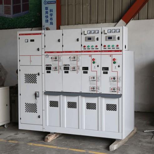
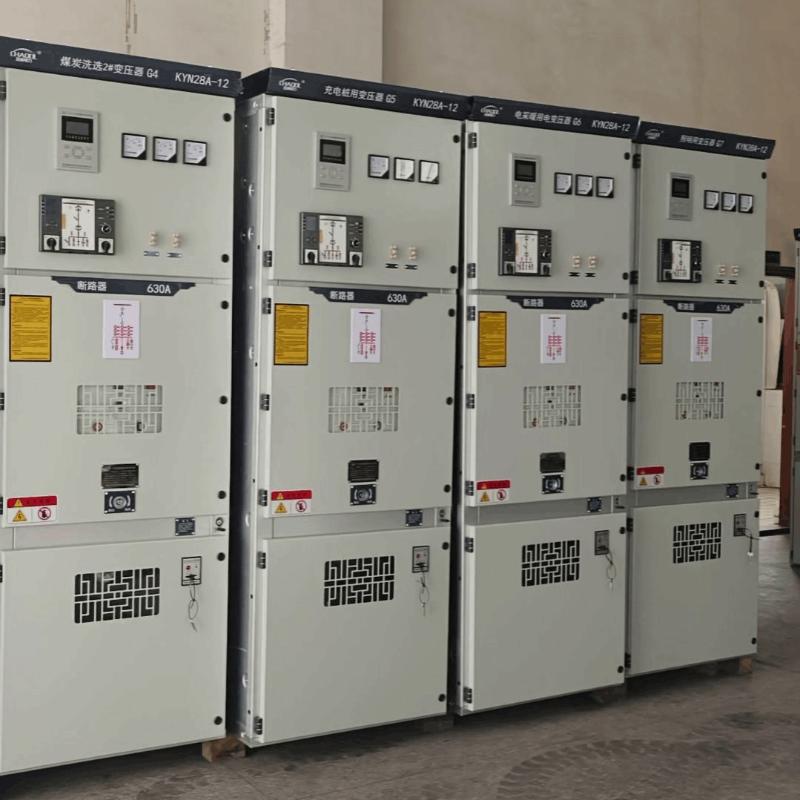
DTU (Distribution Terminal Unit), wanda ita ce terminal na substation a cikin sistemas na zama-zama na kashi, ita ce kayan aiki na biyu da aka shiga a switching stations, makarantun kashi, N2 Insulation ring main units (RMUs), da kuma box-type substations. Ita taka rawa daga kayan aiki na farko zuwa master station na zama-zama na kashi. RMUs mai N2 Insulation da ba suka samu DTUs ba suna iya tabbatar da master station, kuma suna gane karfin zama-zama. Idan aka fuskantar RMUs da kyau ta hanyar models da suka samu DTUs, za mu lura, amma ya kamata aiki masu yawa da kuma hada kan jiragen ruwa. A fuskantar RMUs da sabon DTUs ita ce haɗin aiki mai yawa. Daga tarihin aiki, wannan ita ce taron don fuskantar N2 Insulation RMUs da sheltered upright da kuma outdoor upright "three-remote" (telemetry, teleindication, telecontrol) DTUs.
1 Muhimmanci Mai Bincike Don Fuskantar N2 Insulation RMU
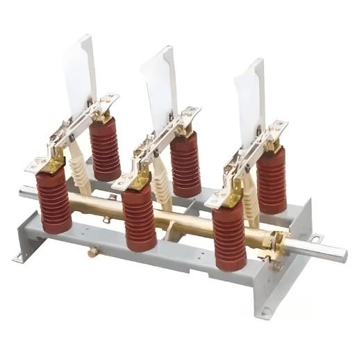
(1) Bincika abubuwan kayan aiki na farko: Bincika abubuwan da ke faruwar da koroshi, jamming, ko kisa. Idan kayan aiki ya danganta da zaman, ba ya fi kyau a fuskanta.
(2) Tabbatar da mekanisomin yanayi: Mekanisomin da ba suka samu yanayi ba suna iya tabbatar da telemetry/teleindication baki daya, amma ba suka iya tabbatar da telecontrol. Fadada fuskanta ya kamata a duba tsohon al'adu na kamfanin.
(3) Tabbatar da terminals na wiring na biyu: Idan ba a gaba da terminals da ake iya gudanar, ba za a iya gudanar DTU. RMUs da wiring na biyu wanda ake gudanar a cikin (wanda ake buƙaci screws don gudanar) ba suka fi kyau a fuskanta. (4) Tabbatar da takamna RMU: RMUs mai N2 Insulation suna da incoming cabinets, outgoing cabinets, da kuma voltage transformer cabinets. Units da 2-in/4-out suna da 7 bays; 2-in/2-out suna da 5 bays. Takamna DTU masu yawa sun hada da 4, 6, 8, ko 10 channels (ba tare da 10). Jumlah channels ya nuna tsarin DTU.
(5) Bincika fadin aikin: Idan aka tabbatar da tsarin DTU, bincika idan aikin RMU ya fi kyau a gudanar. Fadin horizontal mai yawa ya sauka gudanar sheltered upright; babu, ya kamata outdoor upright. Don sheltered upright, bincika idan an samu door na side cabinet. Idan DTU ya fita ne a nan kawai ma a nan door na side, ya kamata a yi kawo-karfi. Outdoor upright installations suna buƙata cabinet na gaba, wanda ya sauka rara, ya sauka nasararsa, da kuma ya sauka foundation work. Foundation placement ya kamata a duba tsohon al'adu, proximity to voltage transformer compartments (cables masu yawa da kasa), da kuma options na routing cables.
(6) Bincika availability na voltage transformer: Current transformers suna bayar current na measurement zuwa protection devices da DTUs. Hanya RMU bays suna da current transformers, voltage transformers ba ake tabbatar da su ba. Voltage transformers suna bayar power zuwa devices (line loss modules, power supplies, etc.) da kuma instruments (voltage meters, power meters), suna bayar 220V AC, zero-sequence voltage, da kuma DTU measurement voltage. Through power modules, suna bayar operating power, DTU power, teleindication power, da kuma communication power indirectly. RMUs da ba suka samu voltage transformers (wanda ke iya bayar power zuwa protection devices ne da current transformers) ba suka fi kyau a fuskanta. Wasu RMUs suna da voltage transformers da ratio 10/0.22 wanda ke buƙata replacement da 10/0.22/0.1 ratio units. Da kuma, bincika idan capacity na voltage transformer da ke ciki ya fi kyau don added DTU load (typically ≤40 VA).
(7) Tabbatar da abubuwan kayan aiki na bays: Electric-operated circuit breakers da load switches suna amfani da control cables masu sama (load switches basu na signal wire "energy stored"). Manual load switches suna buƙata position signals da kuma measurement lines connected to DTU terminals.
(8) Identify safety hazards: Bincika potential construction hazards da kuma develop appropriate safety measures.
2 Gargajiya Masana
(1) Zabi DTU: Bayan bincika, tabbatar da model na DTU mai yawa (channel count). Don configurations masu yawa 2-in/4-out, 6-channel ko 8-channel DTUs suna fi kyau.
(2) Control cables: Wadannan suna gudanar terminals na RMU zuwa terminals na DTU, wadannan suna form various circuits:
Signal circuits: Suna bayar switch positions (closed/open position, energy stored, remote/local status, etc.). Typically use 12×1.5 mm² control cables. Position signals for voltage transformer compartment switches have limited value and are generally not installed.
Measurement circuits: Suna da voltage da kuma current measurement (load current and zero-sequence current). Monitor grid parameters to calculate power values and detect abnormalities (phase loss, imbalance, overload). These activate DTU protection functions (three-stage current protection, voltage protection, zero-sequence protection). Typically use 3-4 cores of 6×2.5 mm² cables connecting phase current transformers (UVW three-phase or UW two-phase) to DTU terminals. 2-in/4-out configurations require six 6×2.5 mm² cables. An additional 6×2.5 mm² cable connects voltage transformer 100V terminals to DTU terminals. Many RMUs lack zero-sequence transformers since cable networks have low ground fault probability.
Control circuits: Suna iya remote/local control of circuit breakers or load switches. Typically use 3 cores of 12×1.5 mm² cable.
Power circuits: Suna bayar power zuwa modules like power supplies. Typically use 2 cores of 6×2.5 mm² cable.
Don configurations masu yawa 2-in/2-out da 2-in/4-out RMU, required control cable specifications and reference lengths are shown in Table 1.
| No. | Model na Kable na Gaba | Tushen Kirkiyar Kable na Gaba na DTU (m) | Tushen Kirkiyar Kable na Gaba na DTU na Waje (m) | ||
| 2-Inlet & 4-Outlet | 2-Inlet & 2-Outlet | 2-Inlet & 4-Outlet | 2-Inlet & 2-Outlet | ||
| 1 | 6×2.5mm2 | 35 (Jami'ar tushen kabilu 7) | 25 (Jami'ar tushen kabilu 5) | 50 (Jami'ar tushen kabilu 7) | 35 (Jami'ar tushen kabilu 5) |
| 2 | 12×1.5mm2 | 33 (Jami'ar tushen kabilu 6) | 22 (Jami'ar tushen kabilu 4) | 40 (Jami'ar tushen kabilu 6) | 30 (Jami'ar tushen kabilu 4) |
Daga wadannan:
① Don kablubin kontrolu da 12×1.5 mm²: Yawan kablubin yana haɗa zuwa kontrolu na gaba mai girma, kontrolu na gaba mai rufin, mazaunin adadin gaba/na gaba, kuma wasu abubuwa. Wannan shi ne ya haɗa zuwa DTU ta hanyar terminal blocks, zai taimaka don ci gaban ruwa. Wasu abubuwan kablubin suna haɗa zuwa idan mai girma, idan mai rufin, disconnector closed position, grounding disconnector closed position, remote position, energy-stored position, common terminal, kuma wasu abubuwa, wannan shi ne ya haɗa zuwa DTU ta hanyar terminal blocks, zai taimaka don ci gaban alama. Kamar haka, electrically operated load switches suna da cikakken haɗa kamar haka, amma ba a ganin "energy stored" signal wire. Abubuwan kablubin da ba a yi amfani da su ba za su iya bazu. Configuration 2-in/2-out take samu 4 kablubin da dama; configuration 2-in/4-out take samu 6 kablubin. Ba a buƙata kablubin da dama a compartment voltage transformer.
② Don incoming and outgoing line compartments: 6×2.5 mm² kablubin suna haɗa zuwa U, V, W three-phase ko U, W two-phase current transformers and common terminals for each incoming or outgoing line. Three-phase connections take samu 4 cores; two-phase connections take samu 3 cores. Remaining cores are kept as spares. A 2-in/2-out configuration requires 4 cables of this type; a 2-in/4-out configuration requires 6 cables.
③ Don compartment voltage transformer: 6×2.5 mm² kablubi mai yawa take haɗa zuwa U, V, W three-phase 100V and 220V terminals (take samu 5 cores) zuwa terminal DTU. Wannan masu ci gaban voltage suna taimaka don ci gaban power outages and voltage anomalies within the cabinet, supports power calculation, provides sampling for voltage-based relay protection, and supplies power to the power module (which provides operating power to the DTU).
(3) Auxiliary materials: Prepare fireproof sealant, PVC wire marker tubes, cable identification tags, nylon cable ties, wire wrapping tubes, insulation tape, and other auxiliary materials as needed based on actual conditions.
(4) Installation tools: Prepare cable strippers, screwdrivers, multimeters, and other necessary tools.
3 Construction Procedures
Saboda installation DTU take da ita ce de-energized secondary equipment, primary equipment operation remains unaffected. To prevent accidental power interruption to primary equipment during DTU installation and commissioning, the following must be confirmed in advance:
The remote/local switch is set to "local" or "locked" position All relay protection output hard plates have been withdrawn All air circuit breakers except device power supply and AC power supply are disconnected
(1) First, securely mount the DTU and ensure reliable grounding with ground resistance not exceeding 10 Ω.
(2) Connect one end of the prepared control cables to corresponding DTU terminals and the other end to cabinet terminals. Due to mechanical tension in the cables, maintain adequate slack as reserve length. Cable laying and wiring must comply with secondary cable connection requirements. For example: control cables should be neatly and securely bound with nylon cable ties; both ends of cables must have identification tags; exposed wire cores after removing cable insulation should be wrapped with wire wrapping tubes. Since this is retrofit wiring, both ends of each wire core must be clearly marked with PVC marker tubes. Unused wire cores should be insulated with tape to prevent accidental contact.
(3) After completing wiring, verify all connections again to ensure accuracy. Check that no tools or leftover materials remain at the site.
(4) Conduct joint commissioning of the DTU with primary equipment and the distribution automation master station to ensure accurate "three-remote" (telemetry, teleindication, telecontrol) functionality. After verification, label the corresponding remote control hard plates according to line numbers and directions. Settings can be input during the commissioning process. Since factory testing of DTUs can only verify communication functionality (without wiring, the master station cannot see telemetry and teleindication data), on-site joint commissioning is necessary to confirm proper wiring and "three-remote" functionality.
(5) Seal all cable openings and clean the site.
(6) As needed, energize the appropriate air circuit breakers, plates, and switches. After equipment commissioning, do not arbitrarily change plate and switch positions.