• Product
  • Suppliers
  • Manufacturers
  • Solutions
  • Free tools
  • Knowledges
  • Experts
  • Communities
Search


Chopper Control of Separately Excited DC Motor

Encyclopedia
Encyclopedia
Field: Encyclopedia
0
China

A chopper is a device that converts a fixed direct - current (DC) voltage into a variable DC voltage. Self - commutated devices, such as Metal - Oxide - Semiconductor Field - Effect Transistors (MOSFETs), Insulated - Gate Bipolar Transistors (IGBTs), power transistors, Gate - Turn - Off Thyristors (GTOs), and Integrated Gate - Commutated Thyristors (IGCTs), are commonly used in the construction of choppers. These devices can be turned on or off directly via a gate control signal using low - power inputs and do not require an additional commutation circuit, making them highly efficient and practical for chopper applications.

Choppers are typically operated at high frequencies. This high - frequency operation significantly enhances motor performance by reducing voltage and current ripples and eliminating discontinuous conduction. One of the most notable advantages of chopper control is its ability to enable regenerative braking even at very low rotational speeds. This feature is particularly valuable when the drive system is supplied with a fixed - to - low DC voltage source, allowing for efficient energy recovery during braking operations.

Motoring Control

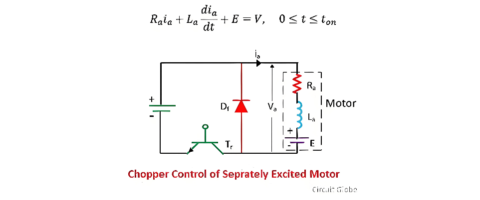
The figure below illustrates a separately - excited DC motor controlled by a transistor chopper. The transistor Tr is periodically switched with a period Tr, remaining in the conducting state for a duration Ton. The corresponding waveforms of the motor terminal voltage and armature current are also depicted in the figure. When the transistor is on, the motor terminal voltage is V, and the operation of the motor can be described as follows:

image.png

During this specific time interval, the armature current increases from ia1 to ia2. This phase is referred to as the duty interval, as the motor is directly linked to the power source during this period. The direct connection allows electrical energy from the source to be transferred to the motor, enabling it to generate mechanical torque and rotate.

When t = ton), the transistor Tr is deactivated. Subsequently, the motor current begins to freewheel through the diode Df. As a result, the voltage at the motor terminals drops to zero within the time interval ton≤t≤T. This interval is known as the freewheeling interval. During this freewheeling phase, the energy stored in the motor's magnetic field and inductance is dissipated through the freewheeling diode, maintaining the flow of current in a closed loop. The motor's operation during this interval can be further analyzed and described by examining the electrical and magnetic interactions within the circuit components.

image.png

Motor current decreases from ia2 to ia1 during this interval.The ratio of duty interval ton to chopper period T is called duty cycle.


image.png

Regenerative Braking

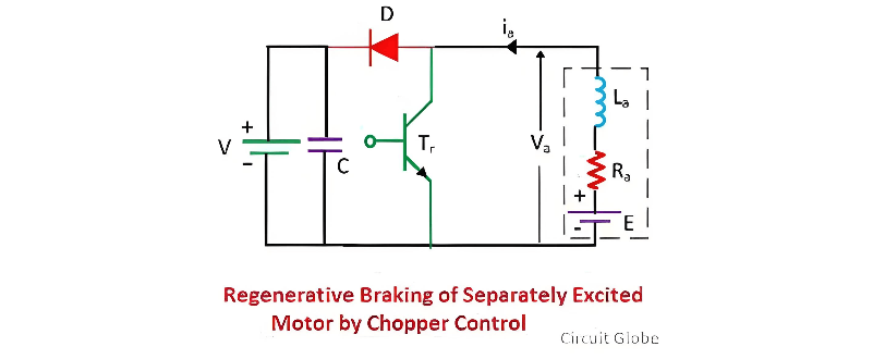
The figure below illustrates a chopper configured for regenerative braking operation. The transistor Tr is cyclically switched with a period T and an on - period ton. Depicted alongside is the waveform of the motor terminal voltage va and the armature current ia under continuous conduction conditions. To enhance the inductance value La, an external inductor is incorporated into the circuit.

When the transistor Tr is turned on, the armature current ia rises from ia1 to ia2. This increase in current occurs as electrical energy is temporarily stored in the inductor and the motor's magnetic field, setting the stage for the subsequent energy conversion process that is characteristic of regenerative braking.

image.png

When the motor operates in the regenerative braking mode, it functions as a generator, converting mechanical energy into electrical energy. A portion of this electrical energy contributes to increasing the magnetic energy stored within the inductance of the armature circuit. Meanwhile, the remaining electrical energy is dissipated as heat within the armature windings and the transistors, due to the inherent resistance of these components.

image.png

When the transistor is switched off, the armature current traverses through diode D and the power source V, decreasing from ia2 to ia1. In this process, both the electromagnetic energy stored in the circuit and the energy generated by the machine are fed back to the power source. The time interval from 0 to ton is defined as the energy storage interval, during which energy accumulates in the system. Conversely, the interval from ton to T is referred to as the duty interval, when energy transfer and system operation occur.

image.png

Motoring and Braking Operation Control

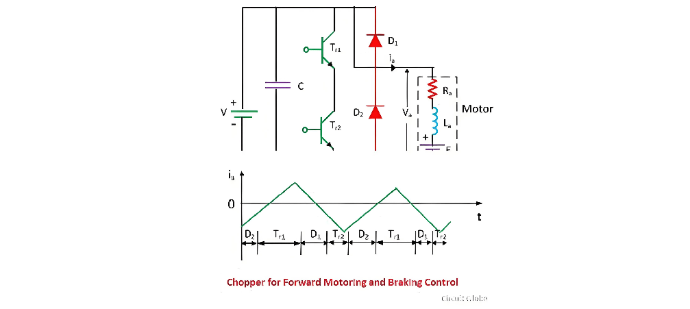
During the motoring operation, the transistor Tr1 is regulated to supply power to the motor, enabling it to rotate forward. Conversely, for the braking operation, the transistor Tr2 takes over control. The transition of control from Tr1 to Tr2 seamlessly switches the system's operation from motoring to braking, and reversing this control transfer shifts it back to the motoring state. This precise control mechanism ensures efficient and reliable operation of the electrical drive system under different working conditions.

Dynamic Control

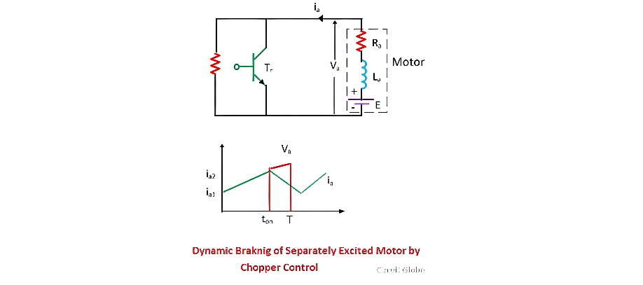
The dynamic braking circuit, along with its corresponding waveform, is depicted in the figure below. In the time interval from 0 to Ton, the armature current ia steadily rises from ia1 to ia2. During this phase, a portion of the electrical energy is stored in the inductance, serving as a reservoir for subsequent operations. Simultaneously, the remaining energy is dissipated as heat within the armature resistance Ra and the transistor TR, a necessary consequence of the electrical resistance present in these components.

image.png

During the time interval Ton ≤ t ≤T the armature current ia drops from ia2 to ia1. In this phase, both the energy generated by the motor and the energy stored in the inductances are dissipated across the braking resistance RB, the armature resistance Ra, and the diode D. The transistor Tr plays a pivotal role in regulating the amount of energy dissipated in RB. By precisely controlling the operation of Tr, one can effectively modulate the power dissipated in RB, thereby influencing the overall braking performance and the effective value of the dissipated energy. This control mechanism allows for fine - tuning of the dynamic braking process, ensuring optimal energy management and system stability.

Give a tip and encourage the author!
Recommended
Composition and Working Principle of Photovoltaic Power Generation Systems
Composition and Working Principle of Photovoltaic (PV) Power Generation SystemsA photovoltaic (PV) power generation system is primarily composed of PV modules, a controller, an inverter, batteries, and other accessories (batteries are not required for grid-connected systems). Based on whether it relies on the public power grid, PV systems are divided into off-grid and grid-connected types. Off-grid systems operate independently without relying on the utility grid. They are equipped with energy-s
Encyclopedia
10/09/2025
How to Maintain a PV Plant? State Grid Answers 8 Common O&M Questions(2)
1. On a scorching sunny day, do damaged vulnerable components need to be replaced immediately?Immediate replacement is not recommended. If replacement is necessary, it is advisable to do so in the early morning or late afternoon. You should contact the power station’s operation and maintenance (O&M) personnel promptly, and have professional staff go to the site for replacement.2. To prevent photovoltaic (PV) modules from being hit by heavy objects, can wire mesh protective screens be install
Encyclopedia
09/06/2025
How to Maintain a PV Plant? State Grid Answers 8 Common O&M Questions(1)
1. What are the common faults of distributed photovoltaic (PV) power generation systems? What typical problems may occur in various components of the system?Common faults include inverters failing to operate or start due to voltage not reaching the startup set value, and low power generation caused by issues with PV modules or inverters. Typical problems that may occur in system components are burnout of junction boxes and local burnout of PV modules.2. How to handle common faults of distributed
Leon
09/06/2025
Short Circuit vs. Overload: Understanding the Differences and How to Protect Your Power System
One of the main differences between a short circuit and an overload is that a short circuit occurs due to a fault between conductors (line-to-line) or between a conductor and earth (line-to-ground), whereas an overload refers to a situation where equipment draws more current than its rated capacity from the power supply.Other key differences between the two are explained in the comparison chart below.The term "overload" typically refers to a condition in a circuit or connected device. A circuit
Edwiin
08/28/2025
Send inquiry
Download
Get the IEE Business Application
Use the IEE-Business app to find equipment, obtain solutions, connect with experts, and participate in industry collaboration anytime, anywhere—fully supporting the development of your power projects and business.