Challenge: Substations, especially aging facilities requiring retrofit (including Gas-Insulated Substations - GIS) or new installations in space-constrained urban environments, face significant pressure to minimize footprint and control costs. Traditional separate Current Transformers (CTs) and Voltage Transformers (VTs) contribute to space inefficiency, higher material/installation costs, and complex maintenance.
Our Solution: Implement a purpose-designed, compact Plug-and-Play Combined Instrument Transformer (CIT) solution. This innovative approach integrates CT and VT functionality into a single, optimized device, delivering substantial benefits from both an economic and spatial perspective.
Core Features & Economic/Space Optimization Strategy
Radical Footprint Reduction (Space Optimization):
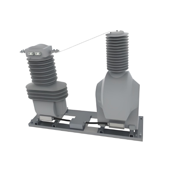
Single Unit Design: Replaces the traditional, spatially separated CT and VT units with one integrated device.
Compact Enclosure: Engineered specifically for tight spaces, ideal for congested substations, brownfield site retrofits (especially within existing GIS bays), and greenfield projects where land is expensive or scarce.
Result: Achieves a 50-70% reduction in the required installation footprint compared to conventional separate units. This frees up valuable real estate for other critical equipment or future expansion.
Lightweight Composite Materials (Cost Optimization - CapEx):
Material Innovation: Utilizes advanced composite polymers or hybrid composites instead of traditional porcelain or heavy metal housings.
Significant Weight Reduction: Dramatically lowers the overall unit weight.
Foundation & Structural Cost Savings: Reduced weight translates directly to simpler, lighter, and less expensive support structures and foundations. This lowers both material and civil engineering costs during installation or retrofit.
"Plug-and-Play" Installation (Cost & Time Optimization - CapEx & OpEx):
Pre-Integrated Design: Factory-assembled and tested CIT unit ensures core CT/VT alignment and calibration are complete.
Simplified Site Work: Reduces on-site assembly complexity and installation time.
Reduced Labor Costs: Faster installation translates to lower labor expenses.
Minimized Downtime (Critical for Retrofits): Especially vital in GIS retrofits or live substation upgrades, where minimizing outage windows is paramount for grid reliability and operator revenue.
Standardized High-Utility Ratio Designs (Cost Optimization - CapEx & OpEx):
Limited Range of Optimized Types: Instead of stocking a vast array of separate CTs and VTs, standardize on a curated portfolio of CIT designs covering the most common voltage levels, current ratings, and accuracy classes (e.g., covering 80% of typical substation requirements).
Streamlined Inventory Management: Utilities and suppliers benefit from drastically reduced SKU counts for instrument transformers.
Reduced Initial CapEx:
Fewer Units: One CIT replaces two devices, lowering the unit purchase count.
Smaller Structures: See Point 2 (Lightweight Materials).
Bulk Procurement Savings: Standardization allows for larger volume purchases per CIT model, leveraging economies of scale.
Reduced Long-Term OpEx:
Simpler Maintenance: Only one unit needs inspection, cleaning, and physical checks instead of two. Access points are consolidated.
Reduced Testing Time & Cost: Only one unit requires primary and secondary injection testing during commissioning and routine maintenance, effectively halving the testing time and associated labor/resource costs compared to separate CTs and VTs.
Optimized Spare Holding: Lower SKU count means fewer different spares required in inventory, reducing tied-up capital and storage space.


