Issues and Countermeasures for 10kV SF₆ Gas-Insulated Common Tank Ring Main Unit (European-Style) Cable Connections

Issues and Countermeasures for 10kV SF₆ Gas-Insulated Common Tank Ring Main Unit (European-Style) Cable Connections
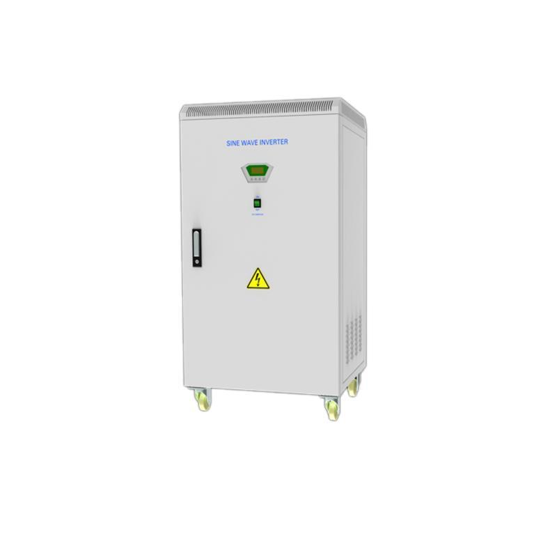
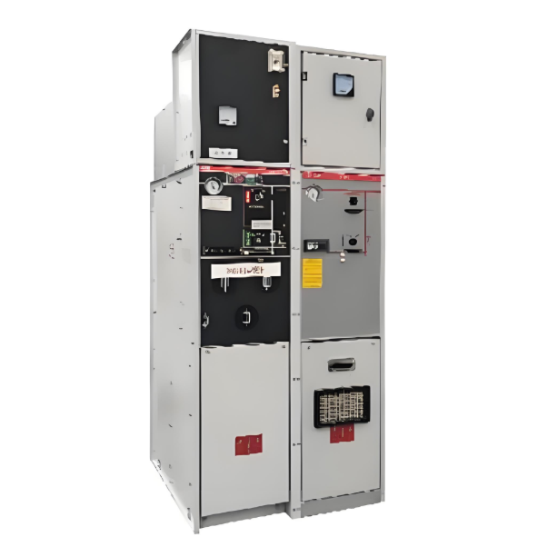
With the extensive use of cable lines in urban distribution networks, 10kV SF₆ gas-insulated common tank Ring Main Units (RMUs) (European-style) are widely adopted as network nodes due to their characteristics of full insulation, complete enclosure, maintenance-free operation, compact size, and flexible installation. These European-style SF₆ common tank RMUs are suitable for coastal areas with humid, salty fog environments and offer high operational reliability.
Recent operational failures of RMUs indicate that most issues stem from problems at the connection points between the RMU bushings and 10kV cables. This is particularly true for indoor and outdoor RMUs handling large currents and large-section cables. When a failure occurs, the entire RMU requires de-energization and replacement, and its cable T-body connector must be re-installed. This significantly impacts power supply reliability and incurs substantial economic losses.
The connection between RMU bushings and 10kV cables is a critical operational weak point. This article analyzes the existing problems and proposes countermeasures.
1. Issues with Common Tank RMUs and Three-Core Cable Connections
Currently, 10kV SF₆ common tank RMUs (European-style) and their associated cable T-body connectors are predominantly European brands. These are primarily designed for single-core cables, which are easier to fix and install, impose no torsional torque on the bushings, ensure good contact between the terminal and bushing, and reduce the likelihood of thermal faults. In contrast, the installation of three-core cables is significantly more complex, leading to several issues absent in single-core installations:
- Three-core cable fixing point is the outer sheath: The individual phases cannot be independently fixed. Even after connection, the cable's own weight or external forces can transmit torsional torque to the bushing sections.
- Phase sequence alignment requires torque: During installation of three-core cables, phase sequence alignment often necessitates applying torque before fixation. Post-installation, the internal stress from this twisting gradually releases, generating a restoring torque that acts on the bushings.
- Limited cable chamber height: The compact cable chamber height of RMUs (designed for single-core cables) restricts the available length of each individual cable core phase.
- Limited adjustment after termination: Once the cable lug is crimped, the installation length is fixed. With shorter individual core lengths (due to space constraints) that are difficult to bend, forcing the T-body connector into position often requires applying excessive pushing, pulling, or levering forces. This risks damaging bushings or causing poor contact.
2. Countermeasures
To address the above issues, countermeasures can be implemented concerning the RMU itself, the T-body connectors, installation practices, and the RMU's civil foundation.
2.1 Ring Main Unit (RMU)
2.1.1 Adequately Increase Cable Chamber Height:
SF₆ common tank RMU cable chambers are typically small (approx. H: 600mm, W: 350mm). This suits single-core cables well but makes installing T-body connectors, especially on large-section cables (240mm² or 300mm²), very difficult for three-core cables. The T-body connector's trifurcating sleeve also needs space, leaving only ~400mm for cable cores. Large-section cores are stiff, and combined with site constraints, achieving correct T-body positioning is challenging.
- Solution: Although common tank RMUs are standardized, installation height can be increased using an extension base. Elevating the chamber height to ~800mm and ensuring the cable clamp's vertical distance from the HV bushing center point is ≥750mm allows core lengths of ~600mm. This facilitates correct T-body installation. Essentially, the extension base lengthens the separated single-phase cores after the three-core cable split, enabling connection similar to single-core cables.
- Benefits: (1) Significantly reduces torsional torque on bushings; (2) Increases installation tolerance, minimizing need for force; lowers gas leakage risk; (3) Facilitates correct positioning of lugs and stress cones.
2.1.2 Consider Bushing Conductivity During RMU Selection:
Standard 630A RMUs often have bolt-type bushings with an outer copper tube diameter of 25mm and threaded inner hole for M16 bolts (conductive area ~289.6mm²). Actual contact area is often smaller due to fit tolerances. When stainless steel bolts are used (due to soft copper), conduction relies only on this end contact. Inside the sealed insulation, heat dissipation is poor. If the lug-to-bushing contact is poor under high currents (>400A), thermal faults occur.
- Solution: For RMUs using 240mm² or 300mm² cables running >400A, select models with 800A-rated bushings (outer copper tube Ø 32mm) to reduce thermal fault risk.
2.1.3 Enhance RMU Bushing Temperature Monitoring:
Sealed common tank RMUs cannot be opened for inspection. Standard IR thermography cannot measure joint temperatures. Adding inspection ports compromises the IP rating.
- Solution:
- Routine checks: Manually feel cable chamber front panel temperature to detect T-body overheating.
- Critical units: De-energize periodically after initial high-current operation to inspect connections for overheating signs.
- Best practice (Technology): Install temperature sensors directly on RMU bushings or T-body connectors for real-time temperature monitoring.
2.2 Cable T-Body Connector
2.2.1 Ensure Quality of Conductive Components:
Switching to stainless steel bolts makes conduction solely dependent on end contact, increasing demands on lug structure/material quality. Common issues found:
Lug contact surface too narrow/hole too large → reduced contact area.
Poor lug material quality, uneven plating.
Mismatch between lug hole taper and double-ended bolt → lug cannot contact bushing properly → conduction only via bolt.
Copper washer too thin/small → cannot ensure parallel lug-to-bushing contact.
All lead to reduced current capacity and thermal fault risk.
- Solution: Specify T-body connector conductive components clearly:
- Lug contact surface width: 25mm or 32mm (match bushing conductive area).
- Lug material: T2 copper (>99.9% Cu, electrolytic, molded, annealed). Tin or silver plating.
- Washer: Large surface, ≥3mm thick to ensure good pressure contact.
2.2.2 Select Soft-Material T-Body Connectors to Ease Installation:
EPDM or rigid plastic/rubber T-bodies are hard/brittle, difficult to adjust during installation (especially large cores/stress cones/insulation), and hard to verify positioning. Poor elasticity/radial force risks long-term interface separation and tracking.
- Solution: Choose Silicone Rubber T-body connectors for common tank RMUs. Benefits: Soft, elastic → easy positioning adjustment; Excellent radial force and uniformity → good sealing, prevents tracking; Sufficient mechanical strength for RMU chambers.
2.3 Site Installation Practices
2.3.1 Secure Cable Entry Point:
Secure the three-core cable entering the RMU directly below the HV bushings using a cable clamp. Avoid tilting or unsupported cable entry. Unsecured cables impose torsional/pulling forces, potentially compromising bushing/seal integrity → SF₆ leakage, bushing cracks, HV faults.
- Position cores vertically and symmetrically; minimize twisting.
- Place the branch glove and cable clamp as low as possible (≥750mm vertical distance from bushings).
- Site Process: After pulling cable through foundation into chamber, cut off any damaged cable end. Verify phase sequence. Align cable entry angle so cores are straight towards bushings. If angle is excessive, retract cable to trench/pit, correct angle, then re-insert and clamp firmly. Double-fixing: Where possible, add a second clamp point (e.g., fixing beam in cable pit below) to secure the outer sheath further.
2.3.2 Cable Phase Separation and Preparation:
- Fix cable branch glove using clamp before trimming core lengths.
- Align B phase with B bushing.
- Slightly bend A/C phases outward at the root before vertically aligning them with their bushings.
- Place termination bolt into bushing, hang lug loosely on it.
- Cut core ends to exact required length after verifying alignment.
- Crucial: Fix cable before final trimming. Failure to do so results in inconsistent core lengths → bushing stress and poor contact.
- Peeling/Cleaning Process:
- Follow T-body manufacturer's peeling dimensions exactly.
- Avoid damaging inner layers while peeling outer layers.
- Absolutely prevent longitudinal scratches on core insulation → prevents internal tracking.
- Use manufacturer-supplied cleaning paper. Avoid other solvents like industrial alcohol.
- Use polyfluoroether-based lubricant (compatible with silicone rubber). Avoid silicone grease → mutual dissolution → interface drying → tracking risk.
2.3.3 Stress Cone Installation:
- Ensure stress cone matches cable size → correct interference fit. Too tight: hard install, risk splitting. Too loose: poor sealing, risk surface discharge.
- Position strictly per T-body manufacturer’s instructions (positions relative to insulation and cable core affect stress control/sealing). Minimal tolerance.
- Position stress cone on the vertical section of the cable if possible → ensures best seal.
- Prevent sharp objects from scratching silicone rubber surfaces.
- Apply uniform coating of compatible lubricant on interference fit surfaces.
2.3.4 Ensure Sufficient Conductor Contact Area:
Conductor connection inside the insulation sleeve is invisible/hard to check. Must ensure:
- Lug surface is parallel to bushing conductive surface → minimized stress on bushing.
- Excellent contact to prevent heating.
- Crimping: Crimp lug to core per procedure. Ensure lug face orientation is parallel to bushing plane. After crimp dies close fully, hold pressure for 10-15 seconds. Deburr surfaces. Clean lug and core insulation.
- Connection: Place lug onto bolt, push T-body into bushing → ensure parallel lug-to-bushing contact before tightening.
2.3.5 Ensure Reliable Grounding:
Shielded T-body connectors must be properly earthed using dedicated grounding rings/wires connected to the RMU ground grid. Failure risks:Static charge build-up on surface → shock hazard.
Surface discharge to nearby ground → material electrical erosion.
2.4 Requirements for RMU Civil Foundation
- RMU base typically 300-500mm above ground level.
- Cable pit depth below base should be ≥800mm; strive for 1000mm if site permits.
- Purpose: Provides adequate bending radius for cable entry (especially large sections), allowing near-vertical entry → reduces stress on cable/connection.