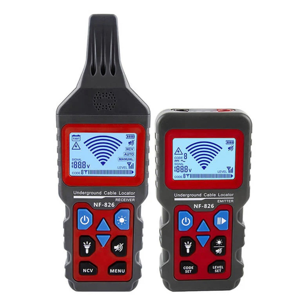
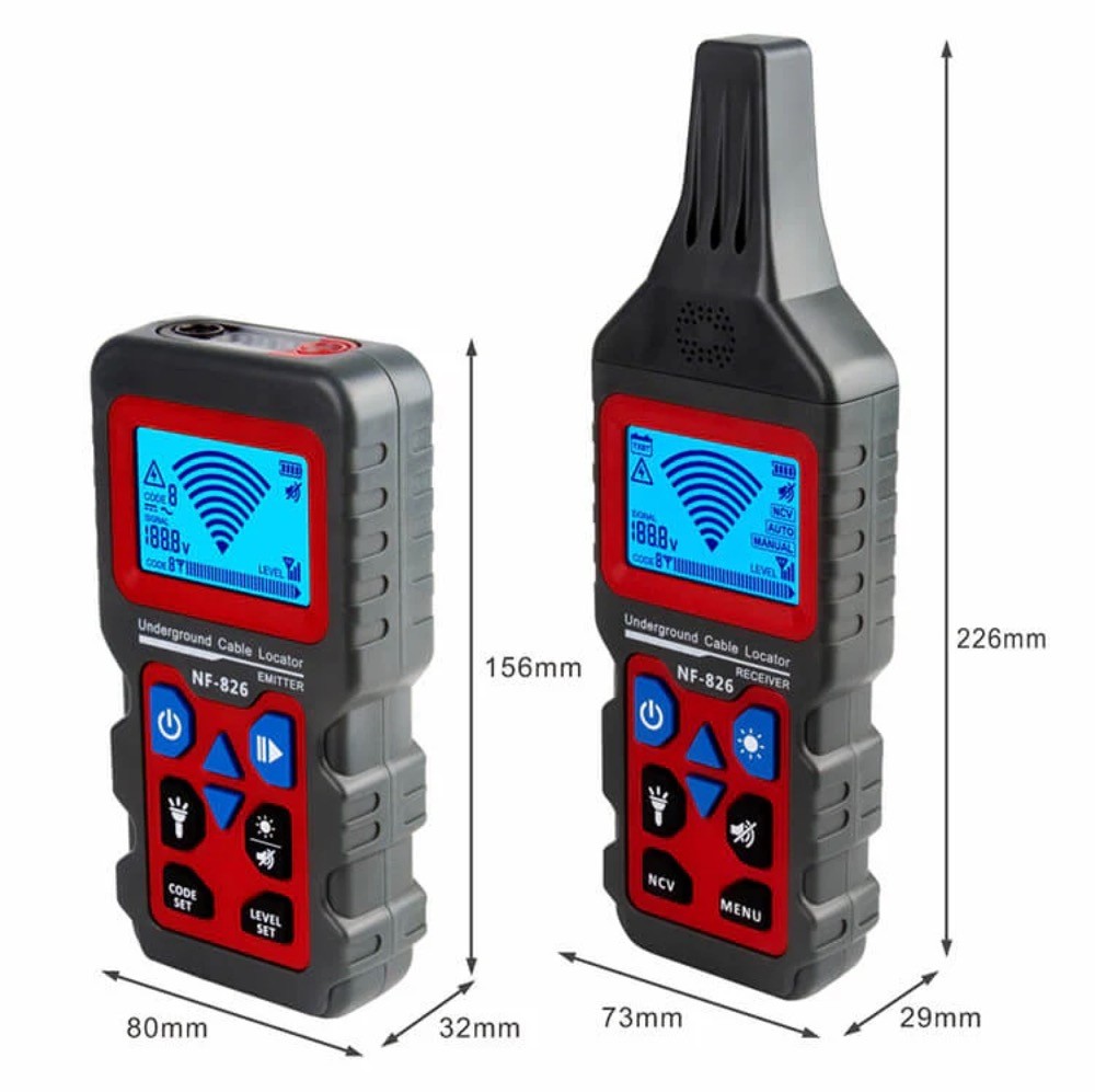
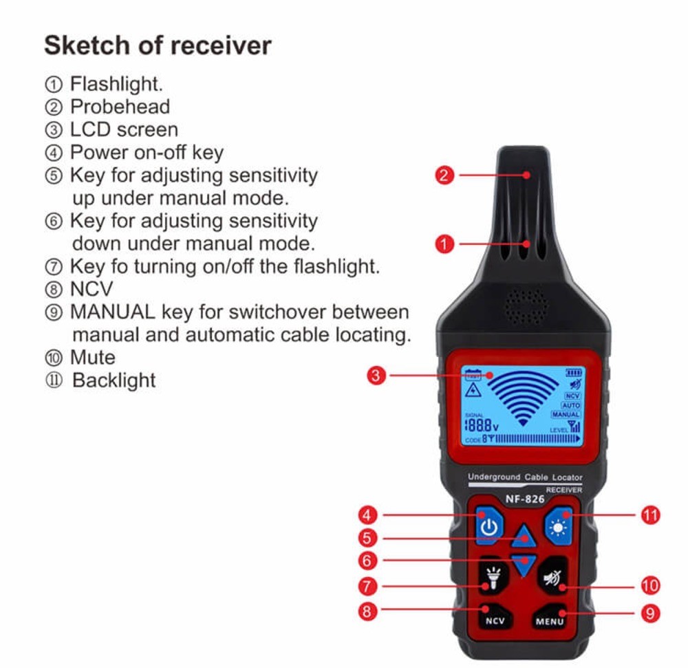
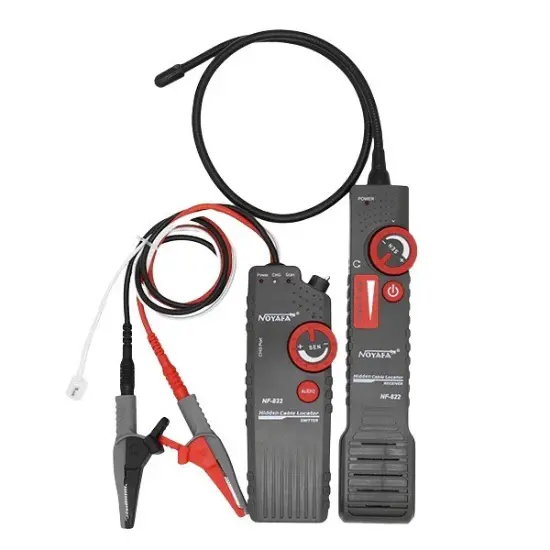
• Wire Tracer for Underground and Wall Electrical Wires and Pipes
  • Wire Tracer for Underground and Wall Electrical Wires and Pipes
  • Wire Tracer for Underground and Wall Electrical Wires and Pipes
  • Wire Tracer for Underground and Wall Electrical Wires and Pipes
Wire Tracer for Underground and Wall Electrical Wires and Pipes
$150.00
Model
NF826
Basic info
Brand Wone
Model NO. NF-826 Wire Tracer for Underground and Wall Electrical Wires and Pipes
Max Depth Range 1000m
Max Cable Length 2m (80 inch)
Series NF
Product Detail

Features

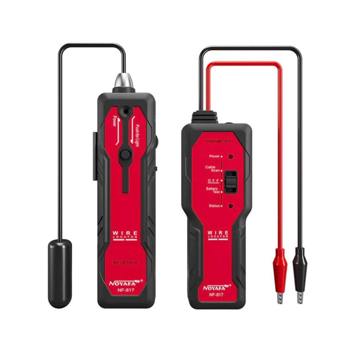
  • Circuit Tracer: Trace circuits and find electrical wires and metal (copper, network, power) cables in drywall or underground. The Max detection range is 2m (80in).

  • Wiring Fault Locator: Tone locating faults like breaks, open circuits, and short circuits in wires and cables. Flexible scanning strength for various environments.

  • Breaker Finder: Attach the transmitter device to a socket via adapters. Locate socket breakers on the box with one tap.

  • Voltmeter: The transmitter has an integrated AC / DC voltmeter for linear measurement of 12-400V DC/AC voltage.

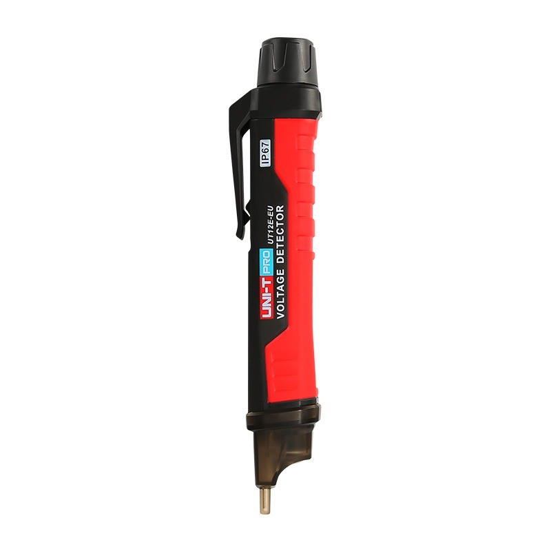
  • Electricity Detector: The receiver (the tone probe) can detect AC voltage over 60V without touching the object.

  • Pipe Locator: Detect the wiring and direction of underground water, heating, and gas pipelines without breaking the lawn and floor. Locate the breakpoints in the pipe easily.

  • A Built-in LED Light: An internal LED light illuminates the dark environment for easy operation.

  • Certification: Passes RoHS, FCC, and CE compliance testing.

  • Fair Price: Compared to expensive Klein and Fluke wire tracers,  NF-826 is a lot more friendly to your budget.

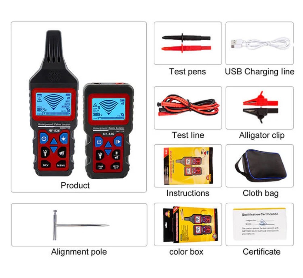
  • Versatile Accessories for Precision: Provide a comprehensive set of accessories tailored for diverse scenarios, ensuring your wire tracing needs are met with precision and efficiency. Elevate your experience with our all-in-one solution for seamless connectivity troubleshooting.

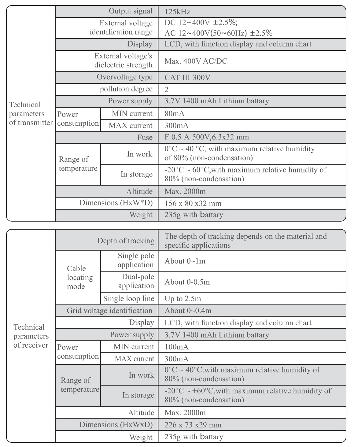
Techical parameters

1718692959495.jpg

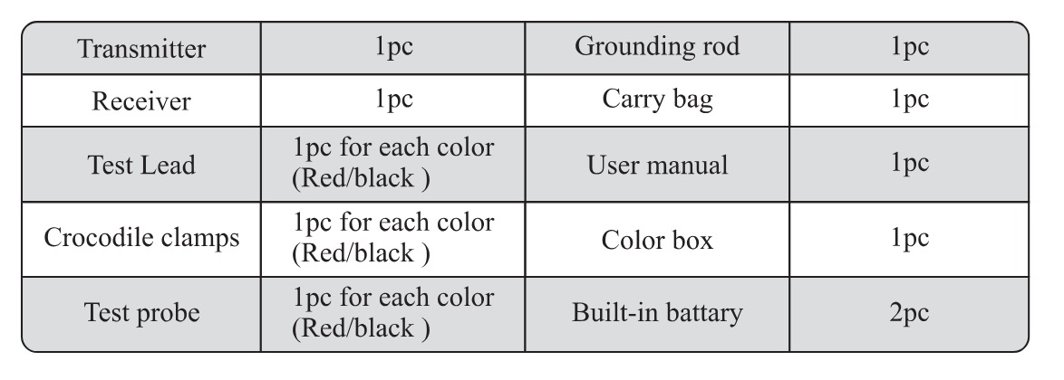
Accessories

1718692985085.jpg

How is the transmitter inductively coupled in a wire tracker?

Inductive Coupling

Inductive coupling is a method of transmitting signals to a target wire through electromagnetic induction without the need for direct contact with the wire. Instead, the signal is transmitted via the alternating magnetic field generated by the transmitter. Here's the process:Generation of Alternating Magnetic Field by the Transmitter:

The transmitter contains a coil that produces an alternating current when the transmitter is active. This alternating current creates a varying magnetic field around the transmitter.

Induction of Current in the Target WireWhen the varying magnetic field passes through the target wire, an induced electromotive force (EMF) is generated within the wire according to Faraday's law of electromagnetic induction. This induced EMF causes an induced current to flow in the wire, thereby impressing the signal generated by the transmitter onto the wire.


Know your supplier
Wone
Main Categories
High Voltage Electrical Apparatus/Low Voltage Electrical Apparatus/Wire cable/Instrument meters/New energy/Tester/Production equipment/Generator/Electrical fittings/Integrated Electrical Equipment
Business Type
Design/Manufacture/Sales
Highest Annual Export (USD)
$50,000,000
Professional Experience
1 years
Workplace
65666m²m²
占位
占位
Related Products
Related Knowledges
What is the difference between a dielectric and an insulator?
Dielectrics and insulators are distinguished primarily by their applications. One of the main differences is that a dielectric can store electrical energy by becoming polarized in an electric field, whereas an insulator resists the flow of electrons to prevent current conduction. Other key differences between them are outlined in the comparison chart below.Definition of DielectricA dielectric material is a type of insulator that contains few or no free electrons. When subjected to an electric fi
Edwiin
08/30/2025
Fault Analysis and Treatment of Oil-Immersed Transformers
Oil Leakage at Welded JointsOil leakage at welded joints primarily stems from poor welding quality, such as incomplete or detached welds, and defects like pinholes and gas pores. Although oil-immersed transformers are initially coated with solder and paint during manufacturing, potentially masking these issues temporarily, the defects tend to surface during operation. Additionally, electromagnetic vibration can cause weld cracks, leading to oil leakage.To resolve such leaks, the first critical s
Edwiin
08/29/2025
What losses occur during operation of the transformer? How to reduce losses?
Transformers experience various types of losses during operation, primarily categorized into two main types: copper losses and iron losses.Copper LossesCopper losses, also known as I²R losses, are caused by the electrical resistance of the transformer windings—typically made of copper. As current flows through the windings, energy is dissipated in the form of heat. These losses are proportional to the square of the load current (I²R), meaning they increase significantly with high
Rockwell
08/29/2025
Cable Fault Detection, Testing, Location and Repair
I. Methods for Cable Testing and Inspection:Insulation Resistance Test: Use an insulation resistance tester to measure the insulation resistance value of the cable. A high insulation resistance value indicates good insulation, while a low value may suggest insulation problems requiring further investigation.Voltage Withstand Test: Apply a high-voltage test using a high-voltage tester to verify whether the cable can withstand high voltage under its rated operating conditions. Under normal circums
Leon
08/29/2025
Cable Quality Inspection and Cable Detection & Testing
Power cable quality inspection and cable testing are conducted to ensure that the cable's quality and performance meet specified requirements, thereby guaranteeing the safe and stable operation of power systems. Below are some common contents of power cable quality inspection and cable testing:Visual Inspection: Check the cable surface for physical defects such as damage, deformation, or scratches to ensure the cable's exterior is intact.Dimensional Measurement: Measure dimensional parameters su
Edwiin
08/29/2025
Transformer Detection, Testing, Maintenance and Servicing
Transformer testing, inspection, and maintenance are essential tasks to ensure normal operation and extend the service life of transformers. Below are some recommended steps:Visual Inspection: Regularly inspect the transformer's exterior, including the enclosure, cooling system, and oil tank. Ensure the enclosure is intact, free from corrosion, damage, or leakage.Insulation Resistance Testing: Use an insulation resistance tester to check the transformer's insulation system. Verify that the insul
Vziman
08/29/2025
×
Inquiry
Download
IEE-Business is dedicated to serving the personnel in the global power industry.
Join IEE-Business, not only can you discover power equipment and power knowledge, but also canhnd like - minded friends!