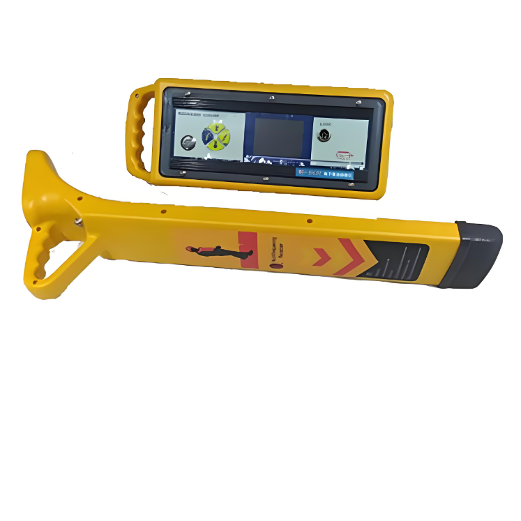
Underground pipeline detector


Key attributes
| Brand | Wone Store |
| Model NO. | WD-2137 Underground pipeline detector |
| Output Voltage | 60V |
| Series | WD-2137 |
Product descriptions from the supplier
Description
WD-2137 underground pipeline detector is a high-tech product designed based on the reflection principle and electromagnetic induction principle of electromagnetic waves in the transmission process, combined with digital filtering, wireless reception and software control.
Specifications
Transmitter technical parameters:
Apply a specific frequency of positioning signal to the pipeline;
Output mode: induction mode, direct connection mode, and clamp mode;
Operating frequency: 577Hz, 815Hz, 8k Hz, 33 k Hz, 65.5kHz, 82k Hz, 133k Hz, three composite frequencies simultaneously output and the selected frequency custom;
Output power: 10W;
Output voltage: 60V;
Maximum output current: 1A;
Power supply: double power supply, lithium battery pack (energy saving and environmental protection);
Continuous working hours: 12 hours at 1W; 8 hours at 5W; 5 hours at 10W;
Ambient temperature: -20℃ -50℃.
Receiver technical parameters:
The receiver has two receiving modes, "basic" and "peripheral". When the mode is "A-frame" mode, the "peripheral" receiving mode can only be entered in the A-frame mode.
Receiving frequency: Receive five kinds of sinusoidal AC signals of low frequency, intermediate frequency, high frequency, radio frequency and 50Hz.
Receiving mode: crest method (horizontal coil), trough method (vertical coil), depth measurement (dual horizontal antenna), current measurement (dual horizontal antenna).
Signal interface: digital size, trapezoidal grating length, sound priority three ways to prompt signal strength at the same time
Display interface: high-brightness LCD, supports working under strong sunlight, and backlighting to ensure normal work at night.
Gain control: manual adjustment, dynamic range 000-100db.
Probe length:
When the metal pipeline is directly connected, the maximum length is 15KM. .
When coupling metal pipelines, one coupling can measure 3Km, and multiple couplings are infinite.
When sensing metal pipelines, one sensing can measure 300m, and multiple sensing is infinite.
Depth measurement:
Direct reading detection depth, range 000-300cm.
80% method to measure the depth, range 000-300cm (coupling) 600cm (direct connection)
Current measurement: direct reading current, range 000-999mA.
Detection accuracy: ±2.5%+5cm (0-2m)
Power supply: imported high-capacity 18650 lithium battery pack, charge and discharge 500 times.
Standby time: more than 12 hours, power prompt.
Overheating and overcurrent: automatic protection.
Working temperature: -10℃—40℃.
Dimension: 650×110×32 mm
Weight: 1.6Kg

Related Products
Related Knowledges
-
 Main Transformer Accidents and Light Gas Operation Issues1. Accident Record (March 19, 2019)At 16:13 on March 19, 2019, the monitoring background reported a light gas action of No. 3 main transformer. In accordance with the Code for Operation of Power Transformers (DL/T572-2010), operation and maintenance (O&M) personnel inspected the on-site condition of No. 3 main transformer.On-site confirmation: The WBH non-electrical protection panel of No. 3 main transformer reported a Phase B light gas action of the transformer body, and the reset was ineff02/05/2026
 -
 Faults and Handling of Single-phase Grounding in 10kV Distribution LinesCharacteristics and Detection Devices for Single-Phase Ground Faults1. Characteristics of Single-Phase Ground FaultsCentral Alarm Signals:The warning bell rings, and the indicator lamp labeled “Ground Fault on [X] kV Bus Section [Y]” illuminates. In systems with a Petersen coil (arc suppression coil) grounding the neutral point, the “Petersen Coil Operated” indicator also lights up.Insulation Monitoring Voltmeter Indications:The voltage of the faulted phase decreases (in01/30/2026
 -
 Neutral point grounding operation mode for 110kV~220kV power grid transformersThe arrangement of neutral point grounding operation modes for 110kV~220kV power grid transformers shall meet the insulation withstand requirements of transformer neutral points, and shall also strive to keep the zero-sequence impedance of substations basically unchanged, while ensuring that the zero-sequence comprehensive impedance at any short-circuit point in the system does not exceed three times the positive-sequence comprehensive impedance.For 220kV and 110kV transformers in new constructi01/29/2026
 -
 Why Do Substations Use Stones, Gravel, Pebbles, and Crushed Rock?Why Do Substations Use Stones, Gravel, Pebbles, and Crushed Rock?In substations, equipment such as power and distribution transformers, transmission lines, voltage transformers, current transformers, and disconnect switches all require grounding. Beyond grounding, we will now explore in depth why gravel and crushed stone are commonly used in substations. Though they appear ordinary, these stones play a critical safety and functional role.In substation grounding design—especially when multiple gr01/29/2026
 -
 Why Must a Transformer Core Be Grounded at Only One Point? Isn't Multi-Point Grounding More Reliable?Why Does the Transformer Core Need to Be Grounded?During operation, the transformer core, along with the metal structures, parts, and components that fix the core and windings, are all situated in a strong electric field. Under the influence of this electric field, they acquire a relatively high potential with respect to ground. If the core is not grounded, a potential difference will exist between the core and the grounded clamping structures and tank, which may lead to intermittent discharge.I01/29/2026
 -
 Understanding Transformer Neutral GroundingI. What is a Neutral Point?In transformers and generators, the neutral point is a specific point in the winding where the absolute voltage between this point and each external terminal is equal. In the diagram below, pointOrepresents the neutral point.II. Why Does the Neutral Point Need Grounding?The electrical connection method between the neutral point and earth in a three-phase AC power system is called theneutral grounding method. This grounding method directly affects:The safety, reliabilit01/29/2026
Related Solutions
-
 Dedicated Vacuum Contactor Solution for Port Shore Power SystemsI. Background and ChallengesShore power systems have become core technical equipment for ports to reduce carbon emissions and noise pollution. However, these systems face two major challenges in the harsh operational environment of ports:Severe Environmental Corrosion: High humidity and salt spray in port areas cause serious corrosion to metal components and enclosures of electrical equipment, significantly impacting electrical lifespan and operational reliability.High Switching Requirements:09/13/2025
 -
 ABB Vacuum Contactor KC2 Power Supply System Technical Transformation PlanIssue OverviewThe 10kV air compressor starting system of a company utilizes the ABB vacuum contactor KC2 as the control component for the operating circuit. The dedicated wide-voltage power supply module paired with this contactor presents the following issues:Frequent failures: The power supply module fails to properly transition the voltage from 300V to 12V, resulting in fuse blowouts.Poor heat dissipation: Enclosed installation of the module leads to insufficient heat dissipation, acceler09/13/2025
 -
 Solution for Medium-Voltage Motor Control and Protection Using Vacuum Contactor-Fuse (VCF) in a Coal Conveying System1.Project BackgroundA coal conveying system comprises 15 belt conveyors driven by medium-voltage motors. The system operates under complex conditions, with motors often subjected to heavy loads and frequent starts. To address these challenges and achieve effective control and reliable protection during motor startup, the project comprehensively adopts Vacuum Contactor-Fuse (VCF) combination devices for the 6kV medium-voltage motor power distribution. This solution details the technical features,09/13/2025


