Voltage stabilization and compensation overhead voltage regulator 6kV 6.35kV 11kV 15kV 22kV 33kV – IEEE for Power Industry

Key attributes
| Brand | ROCKWILL |
| Model NO. | Voltage stabilization and compensation overhead voltage regulator 6kV 6.35kV 11kV 15kV 22kV 33kV – IEEE for Power Industry |
| Rated voltage | 22kV |
| Phases | Single-phase |
| Series | RVR |
Product descriptions from the supplier
Product Description
pioneer and the first source factory in China's voltage regulator industry, we have been deeply rooted in the sector for decades, accumulating profound technical expertise. Leveraging top-tier R&D capabilities and a mature manufacturing system, our products have gained widespread market trust with reliability and performance that far exceed industry standards.
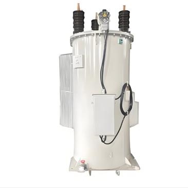
The RVR-1 single-phase step voltage regulator is an advanced tap-changing autotransformer engineered specifically for precise voltage regulation on 11kV overhead distribution lines. Exclusively manufactured in China with rigorous quality control, this compact and reliable device automatically adjusts line voltage within a ±10% range via 32 fine-tuning steps (approximately 5/8% per step), effectively mitigating voltage fluctuations caused by varying load conditions or grid instability.
Compatible with both 50Hz and 60Hz power systems, the RVR-1 offers flexible installation options—supporting pole-mounted, pad-mounted, or substation deployment to adapt to diverse distribution network requirements. Its robust design integrates a durable oil-immersed structure and intelligent tap-changing mechanism, ensuring long-term operational stability and low maintenance needs. Ideal for enhancing power supply quality in rural, suburban, or industrial areas, this regulator delivers consistent voltage output, protecting sensitive equipment and optimizing overall grid efficiency.
Product Features
Precise Voltage Control:32-step tap changer (±10% range) for accurate voltage stabilization.
Wide Compatibility:Supports system voltages from 2,500V to 19,920V (60–150 kV BIL) and currents up to 1,665A.
Advanced Digital Control:Programmable settings for voltage limits, communication protocols, and data logging.
Flexible Installation:Pole-mounted brackets, pad-mounted bolts, or substation bases (elevating platforms optional).
Robust Design:Internal tap windings and optional ratio correction transformer for diverse grid applications.
Advantages
High Reliability: Ensures consistent voltage output in harsh environments.
Customizable :Adaptable to various system voltages and control requirements.
Low Maintenance :Automated tap-changing reduces manual intervention.
Technical Parameters
Available voltage ratings include 50Hz (6kV, 6.35kV, 11kV, 15kV, 22kV, 33kV) and 60Hz (7.62kV, 13.8kV, 14.4kV, 19.92kV, 34.5kV). Custom voltage ratings are available upon request.
Parameter |
Specification |
Model No. |
RVR-1 |
Voltage Rating |
Up to 34.5 kV |
Regulation Range |
±10% (Boost/Buck) |
Tap Steps |
32 steps (approx. 0.625% per step) |
Phase |
Single-phase |
Transformer Type |
Tap-changing autotransformer |
Core Type |
Ring-shaped core |
Cooling Method |
ONAN (Oil-immersed, natural air cooled) |
Winding Configuration |
Two-winding Transformer |
BIL Rating |
60 -150 kV |
Current Rating |
Up to 1665 A |
Frequency |
50 Hz / 60 Hz |
50Hz
Voltage (kV) |
Current (A) |
Capacity (kVA) |
BIL (kV) |
Power Frequency Withstand Voltage (kV) |
Insulation Class |
6/6.35 |
50 |
30/32 |
75/95 |
28 |
A |
100 |
60/64 |
||||
150 |
90/95 |
||||
200 |
120/127 |
||||
300 |
180/191 |
||||
400 |
240/254 |
||||
500 |
300/318 |
||||
600 |
360/381 |
||||
11 |
50 |
55 |
|||
100 |
110 |
||||
150 |
165 |
||||
200 |
220 |
||||
300 |
330 |
||||
400 |
440 |
||||
500 |
550 |
||||
600 |
660 |
||||
15 |
50 |
75 |
125/150 |
50 |
|
100 |
150 |
||||
150 |
225 |
||||
200 |
300 |
||||
300 |
450 |
||||
400 |
600 |
||||
500 |
750 |
||||
22 |
50 |
110 |
|||
100 |
220 |
||||
150 |
330 |
||||
200 |
440 |
||||
300 |
660 |
||||
33 |
50 |
165 |
170/200 |
70 |
|
100 |
330 |
||||
150 |
495 |
||||
200 |
660 |
||||
250 |
825 |
||||
300 |
990 |
60Hz
Voltage (kV) |
Current (A) |
Capacity (kVA) |
BIL (kV) |
Power Frequency Withstand Voltage (kV) |
Insulation Class |
7.62 |
50 |
38 |
60/75 |
20 |
A |
100 |
76 |
||||
150 |
114 |
||||
219 |
167 |
||||
328 |
250 |
||||
438 |
333 |
||||
546 |
416 |
||||
13.8 |
50 |
69 |
95/125 |
38 |
|
100 |
138 |
||||
150 |
207 |
||||
200 |
276 |
||||
300 |
414 |
||||
400 |
552 |
||||
14.4 |
50 |
72 |
|||
100 |
144 |
||||
200 |
288 |
||||
300 |
432 |
||||
400 |
576 |
||||
19.92 |
50 |
100 |
170/200 |
70 |
|
100 |
200 |
||||
167 |
333 |
||||
200 |
400 |
||||
335 |
667 |
||||
34.5 |
50 |
165 |
|||
100 |
330 |
||||
150 |
495 |
||||
200 |
660 |
Application Scenarios
Rural/Urban Power Grids – Compensates for voltage drops in long-distance overhead lines.
Industrial Zones – Stabilizes voltage for heavy machinery and sensitive equipment.
Renewable Energy Integration – Manages fluctuations in solar/wind power-fed grids.
Substations – Enhances voltage control in distribution networks.

Related Products
-
6.35kV 13.2kV 14.4kV 22kV 33kV Oil-immersed self-cooled induction voltage regulator source manufacturer

-
13.2kV 14.4kV 19.92 kV 33kV 34.5 kV Single Phase Pole Mounted voltage regulator control for Precise output voltage regulation

-
13.2kV 13.8kV 14.4kV 19.92kV IEC Standard voltage regulator control compliant for Industrial Manufacturing Industry

-
6kV 6.35kV 7.62kV 13.2kV 13.8kV 14.4 kV Overhead Line Single Phase Automatic Step Voltage Regulator

-
Automatic Tap - Changing Voltage Regulator – 7.62 kV 11kV 13.8 kV 14.4 kV 19.92 kV 34.5 kV, IEEE compliant for Power Industry

-
Continuous / Step voltage regulation step voltage regulator 6kV 6.35kV 11kV 15kV 22kV 33kV – IEEE

-
Single Phase Automatic Voltage Regulator – 7.62 kV 13.8 kV 14.4 kV 19.92 kV 34.5 kV IEC 60076 compliant for Power Industry

Related Knowledges
-
 Impact of DC Bias in Transformers at Renewable Energy Stations Near UHVDC Grounding ElectrodesImpact of DC Bias in Transformers at Renewable Energy Stations Near UHVDC Grounding ElectrodesWhen the grounding electrode of an Ultra-High-Voltage Direct Current (UHVDC) transmission system is located close to a renewable energy power station, the return current flowing through the earth can cause a rise in ground potential around the electrode area. This ground potential rise leads to a shift in the neutral-point potential of nearby power transformers, inducing DC bias (or DC offset) in their01/15/2026
 -
 HECI GCB for Generators – Fast SF6 Circuit Breaker1.Definition and Function1.1 Role of the Generator Circuit BreakerThe Generator Circuit Breaker (GCB) is a controllable disconnect point located between the generator and the step-up transformer, serving as an interface between the generator and the power grid. Its primary functions include isolating generator-side faults and enabling operational control during generator synchronization and grid connection. The operating principle of a GCB is not significantly different from that of a standard c01/06/2026
 -
 Distribution Equipment Transformer Testing, Inspection, and Maintenance1.Transformer Maintenance and Inspection Open the low-voltage (LV) circuit breaker of the transformer under maintenance, remove the control power fuse, and hang a “Do Not Close” warning sign on the switch handle. Open the high-voltage (HV) circuit breaker of the transformer under maintenance, close the grounding switch, fully discharge the transformer, lock the HV switchgear, and hang a “Do Not Close” warning sign on the switch handle. For dry-type transformer maintenance: first clean the porcel12/25/2025
 -
 How to Test Insulation Resistance of Distribution TransformersIn practical work, insulation resistance of distribution transformers is generally measured twice: the insulation resistance between thehigh-voltage (HV) windingand thelow-voltage (LV) winding plus the transformer tank, and the insulation resistance between theLV windingand theHV winding plus the transformer tank.If both measurements yield acceptable values, it indicates that the insulation among the HV winding, LV winding, and transformer tank is qualified. If either measurement fails, pairwise12/25/2025
 -
 Design Principles for Pole-Mounted Distribution TransformersDesign Principles for Pole-Mounted Distribution Transformers(1) Location and Layout PrinciplesPole-mounted transformer platforms should be located near the load center or close to critical loads, following the principle of “small capacity, multiple locations” to facilitate equipment replacement and maintenance. For residential power supply, three-phase transformers may be installed nearby based on current demand and future growth projections.(2) Capacity Selection for Three-Phase Pole-Mounted Tr12/25/2025
 -
 Transformer Noise Control Solutions for Different Installations1.Noise Mitigation for Ground-Level Independent Transformer RoomsMitigation Strategy:First, conduct a power-off inspection and maintenance of the transformer, including replacing aged insulating oil, checking and tightening all fasteners, and cleaning dust from the unit.Second, reinforce the transformer foundation or install vibration isolation devices—such as rubber pads or spring isolators—selected based on the severity of vibration.Finally, strengthen sound insulation at weak points of the ro12/25/2025
Related Solutions
-
 Intelligent Operation Solution for 12kV Vacuum Circuit Breakers: Integrating Real-time Monitoring & Lifetime OptimizationⅠ. Equipment Operation & MaintenanceIntelligent Monitoring System IntegrationMulti-parameter Real-time Monitoring: Embedded sensors (temperature, displacement, Hall effect current sensors) track contact temperature rise, mechanical characteristics (opening/closing speed, overtravel), coil current, and partial discharge signals. Data undergoes preprocessing via edge computing prior to cloud upload.Lifetime Prediction Model: Dynamically evaluates remaining lifespan using electrical wear data06/10/2025
 -
 SF6 Circuit Breaker Solutions for Outdoor Installation (Anti-Pollution & Seismic Resistance)I.Core Challenges in Outdoor InstallationIn high-voltage transmission and distribution systems, SF6 circuit breakers are exposed to complex outdoor environments for extended periods, facing the following critical issues:Pollution & Insulation DegradationDust, salt fog, and industrial pollutants in outdoor environments easily adhere to equipment surfaces. In coastal or industrial areas, pollution levels may reach Class IV, resulting in insufficient creepage distance and triggering flasho05/12/2025
 -
 12kV Indoor Vacuum Circuit Breaker Southeast Asia Solution: Anti-Corrosion Compact Design12kV Indoor Vacuum Circuit Breaker Southeast Asia Solution: Anti-Corrosion Compact DesignⅠ. Executive SummarySoutheast Asia faces rapidly growing electricity demand alongside environmental challenges including high temperatures, humidity, salt spray corrosion, and grid instability. This solution recommends Solid Insulated Pole-Mounted Vacuum Circuit Breakers (VCB) featuring high reliability, compact design, and smart monitoring. Tailored for tropical climates and industrial scenarios, it06/10/2025


