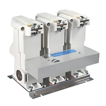
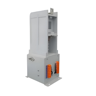
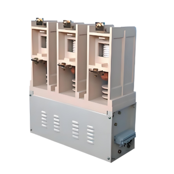
SVC series12kV/400A Vacuum Contactor

Key attributes
| Brand | Wone Store |
| Model NO. | SVC series12kV/400A Vacuum Contactor |
| Rated voltage | 12kV |
| Rated normal current | 630A |
| Rated frequency | 50/60Hz |
| Series | SVC |
Product descriptions from the supplier
Product Description
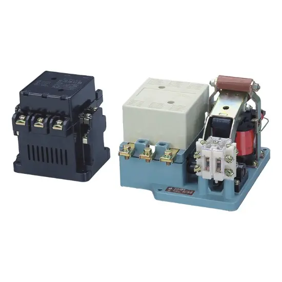
The SVC Series 12kV/400A Vacuum Contactor is a core control device specifically designed for medium-voltage power systems. With a rated voltage of 12kV and a rated current of 400A, it accurately adapts to 12kV-grade medium-voltage power distribution scenarios. Adopting mature vacuum arc-extinguishing technology, it can reliably realize circuit on-off control while featuring excellent safety and durability. Widely used in industrial power distribution cabinets, frequency converter cabinets, power plant auxiliary drive systems and other scenarios, it meets the core requirements of medium-voltage power circuits for stable control and low operation and maintenance costs, providing key power support for the efficient operation of industrial production.
Features
Parameters
Main loop rated parameters |
||
Rated operating voltage |
12 kV |
|
Rated Operating Current (AC-3) |
400A |
630A |
Rated frequency |
50/60 Hz |
|
Related capabilities |
4000 A |
6300 A |
Breaking ability |
3200 A |
5040 A |
Short-term withstand current (4 seconds) |
4000 A |
6300 A |
Switch capacity of a single capacitor bank |
3500 kVar |
|
50Hz power frequency withstand voltage |
42 kV, 1 minute |
|
Lightning shock withstand voltage |
75 kV |
|
Mechanical life |
1,000,000 |
1,000,000 |
Electrical Life (AC-3) |
250,000 |
250,000 |
Rated Operating Frequency (AC-3) |
300 times/hour |
300 times/hour |
Contact resistance |
≤100 µΩ |
≤100 µΩ |
Control loop rating parameters |
||
The coil controls the voltage Ue |
110/220 VAC 50/60Hz |
|
Operating voltage range |
0.8-1.1×Ue |
|
Release voltage |
≤0.5×Ue |
|
Aspiration time |
≤80 ms |
|
Break time |
≤80 ms |
|
Three-phase synchronization |
≤2 ms |
|
Closing bounce time |
≤2 ms |
|
Auxiliary contacts |
3NO+2NC as standard, which can be expanded according to requirements |
|
Application conditions |
||
Operating temperature |
-25~+40ºC |
|
Maximum relative humidity |
90% (at +25ºC) |
|
elevation |
2000 m |
|
weight |
Approx. 30 kg |
|
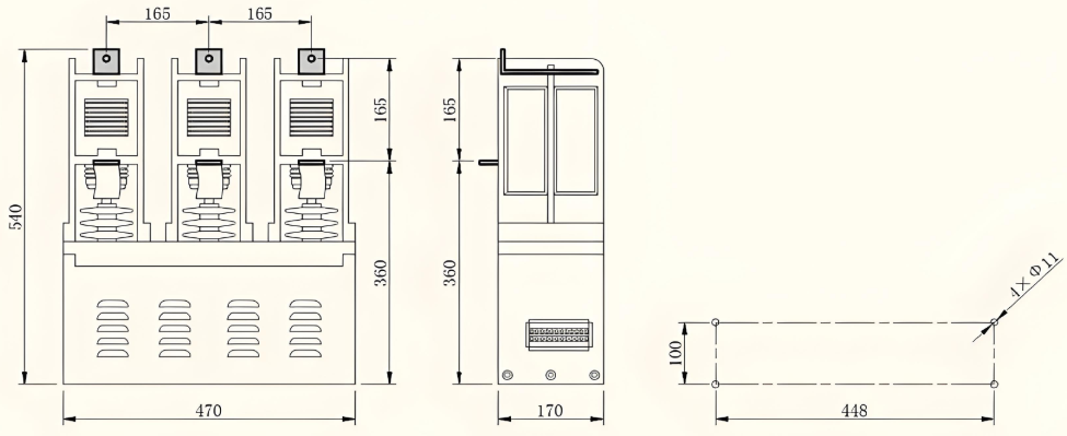
Dimensions (W×H×D) |
470 mm×540 mm×170 mm |
|

Related Products

Related Knowledges
-
 How to Judge, Detect and Troubleshoot Transformer Core Faults1. Hazards, Causes, and Types of Multi-Point Grounding Faults in Transformer Cores1.1 Hazards of Multi-Point Grounding Faults in the CoreUnder normal operation, a transformer core must be grounded at only one point. During operation, alternating magnetic fields surround the windings. Due to electromagnetic induction, parasitic capacitances exist between the high-voltage and low-voltage windings, between the low-voltage winding and the core, and between the core and the tank. The energized windin01/27/2026
 -
 A Brief Discussion on the Selection of Grounding Transformers in Boost StationsA Brief Discussion on the Selection of Grounding Transformers in Boost StationsThe grounding transformer, commonly referred to as "grounding transformer," operates under the condition of being no-load during normal grid operation and overloaded during short-circuit faults. According to the difference in filling medium, common types can be divided into oil-immersed and dry-type; according to phase number, they can be classified into three-phase and single-phase grounding transformers. The groundi01/27/2026
 -
 Impact of DC Bias in Transformers at Renewable Energy Stations Near UHVDC Grounding ElectrodesImpact of DC Bias in Transformers at Renewable Energy Stations Near UHVDC Grounding ElectrodesWhen the grounding electrode of an Ultra-High-Voltage Direct Current (UHVDC) transmission system is located close to a renewable energy power station, the return current flowing through the earth can cause a rise in ground potential around the electrode area. This ground potential rise leads to a shift in the neutral-point potential of nearby power transformers, inducing DC bias (or DC offset) in their01/15/2026
 -
 HECI GCB for Generators – Fast SF6 Circuit Breaker1.Definition and Function1.1 Role of the Generator Circuit BreakerThe Generator Circuit Breaker (GCB) is a controllable disconnect point located between the generator and the step-up transformer, serving as an interface between the generator and the power grid. Its primary functions include isolating generator-side faults and enabling operational control during generator synchronization and grid connection. The operating principle of a GCB is not significantly different from that of a standard c01/06/2026
 -
 Distribution Equipment Transformer Testing, Inspection, and Maintenance1.Transformer Maintenance and Inspection Open the low-voltage (LV) circuit breaker of the transformer under maintenance, remove the control power fuse, and hang a “Do Not Close” warning sign on the switch handle. Open the high-voltage (HV) circuit breaker of the transformer under maintenance, close the grounding switch, fully discharge the transformer, lock the HV switchgear, and hang a “Do Not Close” warning sign on the switch handle. For dry-type transformer maintenance: first clean the porcel12/25/2025
 -
 How to Test Insulation Resistance of Distribution TransformersIn practical work, insulation resistance of distribution transformers is generally measured twice: the insulation resistance between thehigh-voltage (HV) windingand thelow-voltage (LV) winding plus the transformer tank, and the insulation resistance between theLV windingand theHV winding plus the transformer tank.If both measurements yield acceptable values, it indicates that the insulation among the HV winding, LV winding, and transformer tank is qualified. If either measurement fails, pairwise12/25/2025
Related Solutions
-
 Dedicated Vacuum Contactor Solution for Port Shore Power SystemsI. Background and ChallengesShore power systems have become core technical equipment for ports to reduce carbon emissions and noise pollution. However, these systems face two major challenges in the harsh operational environment of ports:Severe Environmental Corrosion: High humidity and salt spray in port areas cause serious corrosion to metal components and enclosures of electrical equipment, significantly impacting electrical lifespan and operational reliability.High Switching Requirements:09/13/2025
 -
 ABB Vacuum Contactor KC2 Power Supply System Technical Transformation PlanIssue OverviewThe 10kV air compressor starting system of a company utilizes the ABB vacuum contactor KC2 as the control component for the operating circuit. The dedicated wide-voltage power supply module paired with this contactor presents the following issues:Frequent failures: The power supply module fails to properly transition the voltage from 300V to 12V, resulting in fuse blowouts.Poor heat dissipation: Enclosed installation of the module leads to insufficient heat dissipation, acceler09/13/2025
 -
 Solution for Medium-Voltage Motor Control and Protection Using Vacuum Contactor-Fuse (VCF) in a Coal Conveying System1.Project BackgroundA coal conveying system comprises 15 belt conveyors driven by medium-voltage motors. The system operates under complex conditions, with motors often subjected to heavy loads and frequent starts. To address these challenges and achieve effective control and reliable protection during motor startup, the project comprehensively adopts Vacuum Contactor-Fuse (VCF) combination devices for the 6kV medium-voltage motor power distribution. This solution details the technical features,09/13/2025


