| Brand | Rw Energy |
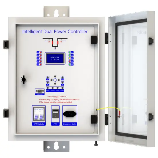
| Model NO. | Intelligent Dual Power Controller |
| Rated voltage | 230V ±20% |
| Rated frequency | 50/60Hz |
| Electric energy consumption | ≤5W |
| Series | RWD-LC |
Description
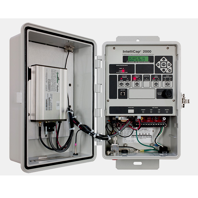
With the development of society, people have higher and higher requirements for power supply reliability. In many cases, two power supplies are used to ensure the reliability of power supply, which requires a product to switch reliably between two power supplies. The intelligent dual power automatic conversion device produced by our company is mainly composed of a high-voltage vacuum circuit breaker with electric dual isolation and a dual power intelligent backup self-input controller. Applied to AC 50HZ, rated voltage 12KV, rated current up to 1250A dual power supply system, when one power failure or undervoltage occurs, the isolation switch automatically switches to the other, the whole process automatically switches to the other normal power supply. Reliable guarantee of continuity of power supply
The controller has a variety of protection functions such as short circuit, three-stage overcurrent, single-phase ground, undervoltage, reclosing and prepaid, which effectively avoids unnecessary re-supply shock when the load fails. When the common power supply fails, the switching device can automatically switch with the standby power supply to ensure reliability and safety. It is especially suitable for important places where power is not allowed, as an important electrical control device to ensure continuous power supply, it is a self-throwing self-restoring dual power automatic switching device matching with high voltage vacuum circuit breaker. The products are widely used in 10kV distribution lines in oil fields and mines, and 10kV lines in industrial and mining enterprises to ensure real-time power supply of important loads. It has the characteristics of small footprint, small investment, convenient debugging and maintenance, and is an ideal switchgear for realizing power supply automation.
Support communication methods: wireless (GSM/GPRS/CDMA), Ethernet, WIFI, optical fiber, power carrier, RS232/485,RJ45, etc., and can access other station equipment (such as TTU, FTU, DTU, etc.).
Main function introduction
1. Protection relay functions:
AST Double line Protection,
49 Thermal Overload (Over load),
50 Three-section of Overcurrent (Ph.OC),
50G/N/SEF Sensitive Earth Fault (SEF),
27/59 Under/Over Voltage (Ph.OV/Ph.UV),
51C Cold load pickup (Cold load).
2. Supervision functions:
60CTS CT Supervision,
60VTS VT Supervision.
3. Control functions:
79 Auto Reclose,
86 Lockout>>>>>>.
circuit-breaker control.
4. Monitoring Functions:
1) Primary currents for Phases and Zero sequence current,
2) Primary PT Voltage,
3) Frequency,
4) Binary Input/Output status,
5) Trip circuit healthy/failure,
6) Time and date,
7) Fault records,
8) Event records.
5. Data Storage functions:
1) Event Records,
2) Fault Records,
3) Measurands
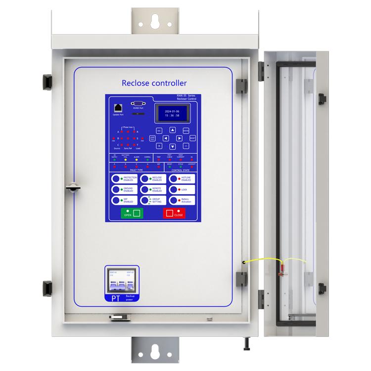
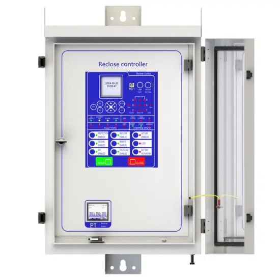
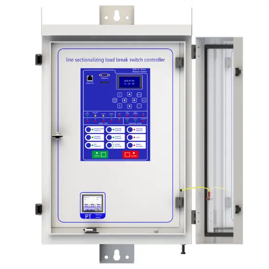
Technology parameters

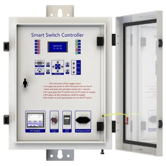
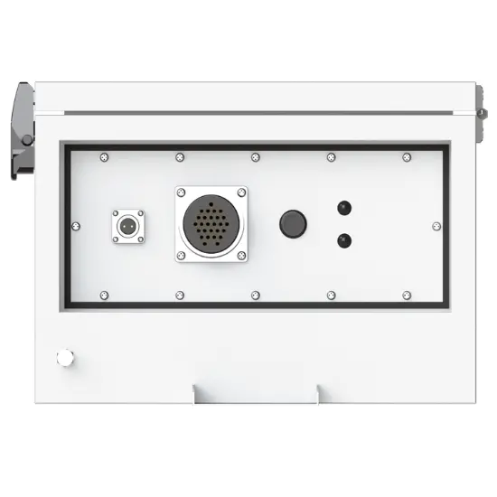
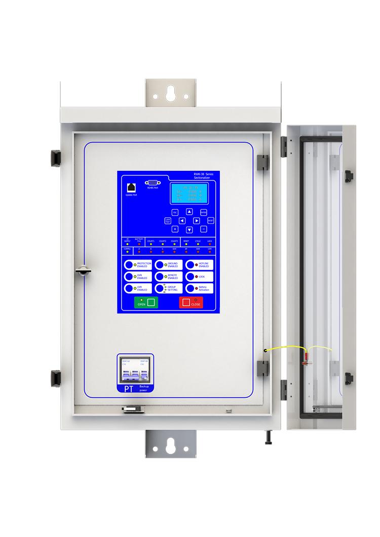
Device structure


About customization
The following optional functions are available: Upgrade SMS Function. Upgrade RS485/RS232 socket.
For detailed customization, please contact the salesman.
Q: What is a high voltage dual power switch?
A: The high-voltage dual power switch is a device used to automatically switch between two high-voltage power supplies. When one power supply fails (such as power failure, abnormal voltage, etc.), it can quickly switch the load to another normal power supply to ensure the continuity of power supply.
Q: Where is it mainly used?
A: In hospitals, data centers, large factories and other places where continuity of power supply is highly required. For example, during hospital surgery, a sudden power outage may endanger the patient's life, and the use of high-voltage dual power switch can avoid this situation.
Q: How fast does it switch?
A: Generally speaking, the switching time can reach the millisecond level, which can minimize the time of load power failure and avoid damage to the equipment.

Sure, this device cannot be upgraded online, but it requires offline firmware version upgrade using a burning device to upgrade more features or fix known bugs. As this device is a customized product, you need to provide us with the device's model number and version number when upgrading. Once we have determined the upgrade plan, we will contact you and provide you with the burning device and firmware upgrade package needed for the upgrade.
Three-Section Overcurrent Protection is a coordinated protection scheme widely used in power systems to detect and isolate faults (e.g., short circuits) while ensuring selective tripping. It consists of three stages with distinct operating characteristics based on current magnitude and time delay:
Function: Responds immediately to severe overcurrents exceeding a high-set threshold (e.g., 5–10 times the rated current).
Purpose: Rapidly clears close-in faults (near the protection device) to prevent equipment damage.
Key Feature: No intentional time delay (operates in milliseconds).
Function: Triggers after a predefined short delay (e.g., 0.1–0.5 seconds) for moderate overcurrents (e.g., 2–5 times the rated current).
Purpose: Handles faults farther from the protection device, allowing downstream breakers to clear localized faults first (selectivity).
Coordination: Employs a time-graded scheme—higher fault currents (closer faults) trip faster, while lower currents (remote faults) trip slower.
Function: Activates after a longer time delay (e.g., several seconds) for low-magnitude overcurrents (e.g., 1.2–2 times the rated current).
Purpose: Serves as a backup for primary protection (Sections I/II) and addresses overloads or persistent faults.
Characteristic: May use an inverse-time curve (trip time decreases as current increases).
Coordination Principle
The three sections work hierarchically:
Section I clears severe faults instantly.
Section II handles moderate faults with short delays, prioritizing system selectivity.
Section III provides backup protection, ensuring reliability if upstream protections fail.
This layered approach minimizes outage scope, balances speed and selectivity, and enhances grid stability.
It supports universal input ranges (e.g., AC 0-600V, DC 0-1000V) and wide power supply (AC 85-265V), compatible with 110V/220V/380V power systems in Europe, America, Asia and other regions, meeting global industrial application needs.