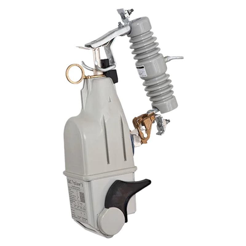
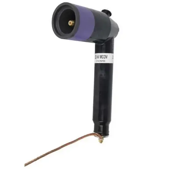
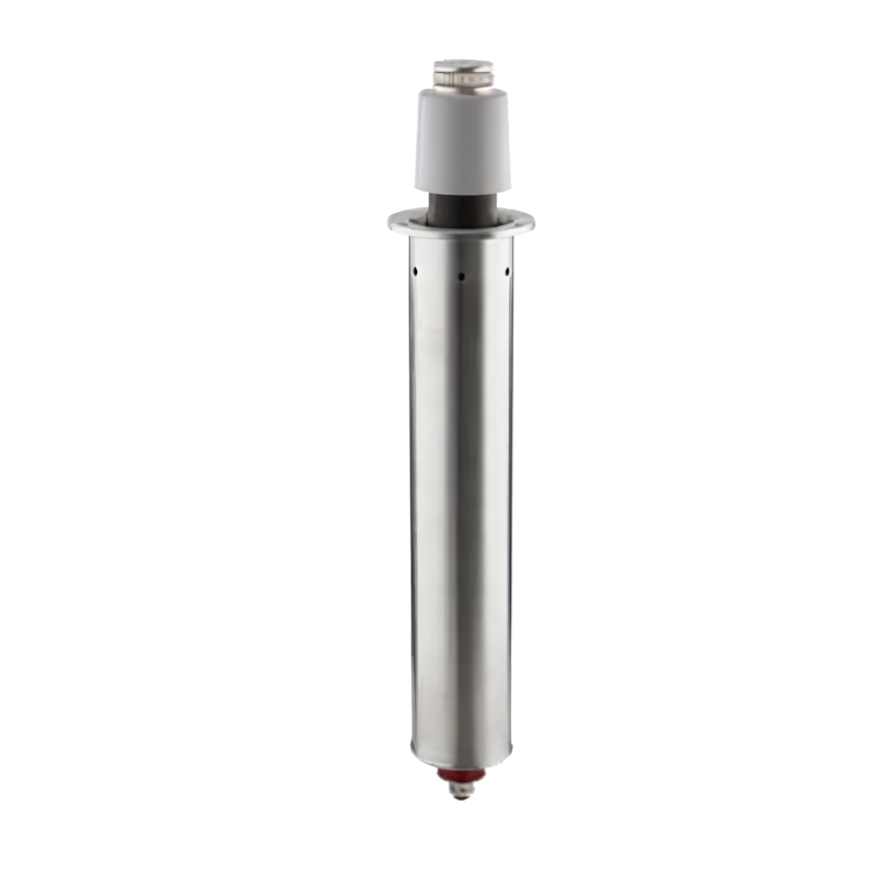
Cutoto-Mounted Reclose
Key attributes
| Brand | RW Energy |
| Model NO. | Cutoto-Mounted Reclose |
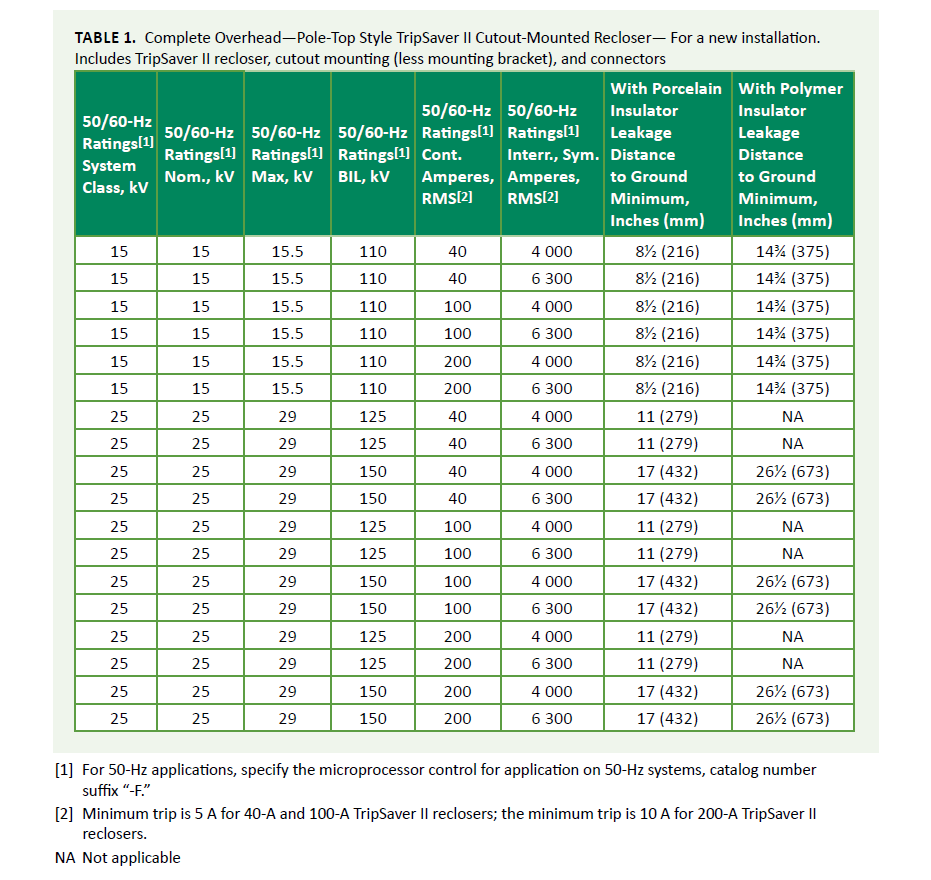
| Rated voltage | 15kV |
| Rated normal current | 40A |
| Rated short circuit breaking current | 4kA |
| Series | TRIPSAVER II |
Product descriptions from the supplier
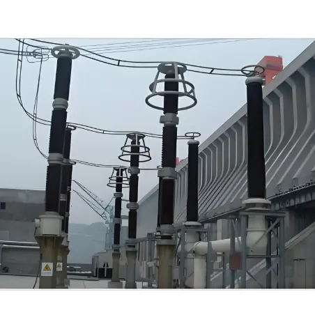
TripSaver II Cutout-Mounted Recloser enables utilities to improve reliability for overhead lateral circuit protection at 15 kV and 25 kV by combining the best aspects of fuse-saving and fuse-blowing. TripSaver II reclosers keep the power on for more customers and avoid costly truck rolls for utilities. This strategy adds an additional reclosing device as close as possible to the source of the problem, so only customers on the faulted lateral are affected. Power can be restored automatically for temporary faults, avoiding sustained outages and reducing momentary outages on feeders by "blinking" only customers on the faulted lateral. Utilities will see immediate reduction in the frequency of sustained outages on their system and a dramatic improvement of reliability scores.
Key Features of Cutout-Mounted Reclosers
1. Automatically Distinguishes & Handles Temporary/Permanent Faults, Enabling "Self-Healing"
When faults (e.g., short circuits, overloads) occur in the line, it quickly interrupts fault current (response time in milliseconds) to prevent fault spread.
For over 80% of temporary faults in power systems (e.g., lightning strikes, momentary tree contact, brief bird-caused short circuits), it automatically attempts ~3 reclosure cycles (configurable count). If the fault clears, power is restored without manual intervention.
If the fault is permanent (e.g., line breakage, equipment damage), it automatically "locks out" (forming a visible circuit gap) after failed reclosures. This completely isolates the faulty section to avoid impacting the entire line, while helping maintenance personnel quickly locate the fault point.
2. Directly Adapts to Existing Lines, No Additional Infrastructure for Installation
No modification to existing lines is required. It can be directly installed on the fuse base of distribution lines (replacing traditional fuses), utilizing the original line’s installation space and wiring.
Compact in size, with no complex wiring or independent cabinets. On-site installation only requires standard electrical tools and can be completed by 1-2 maintenance staff. It supports mainstream low-voltage distribution line voltage levels (e.g., 15kV/25kV).
3. Significantly Improves Power Supply Reliability, Reducing Outage Impact
Reduces unnecessary outage duration: Temporary faults are resolved automatically within seconds, eliminating the need to wait for manual repairs (e.g., avoiding prolonged blackouts across an area after a lightning strike).
Lowers outage frequency: By isolating permanent faults, only the branch line with the fault is affected (not the entire main line), minimizing the outage scope.
Industry data shows it can reduce the distribution line's SAIDI (System Average Interruption Duration Index) by 80% and SAIFI (System Average Interruption Frequency Index) by 60% especially effective for fault-prone branch lines.
4. Safe Arc Extinction + Visual Fault Identification, Reducing Maintenance Risks
Adopts vacuum interrupter technology: Arc extinction occurs internally during fault interruption, eliminating sparks and high-temperature debris (common with traditional fuses) to prevent fires or burns.
After locking out due to permanent faults, it forms a visible mechanical gap (e.g., the physical gap after contact disconnection). Maintenance personnel can judge the fault status visually without live testing, reducing electric shock risks.
5. Low-Cost Maintenance, Reducing Labor & Resource Consumption
No frequent on-site replacements: Traditional fuses require staff to travel to the site for replacement after faults. This device handles temporary faults automatically, and only one on-site reset is needed for permanent faults—reducing over 90% of "unnecessary maintenance trips".
No additional energy consumption: It does not require batteries or external power, relying on the line’s own electricity to power the internal microprocessor—lowering long-term operating costs (e.g., a device from a leading brand can recover its cost after just 4 avoided maintenance trips).
6. Supports Smart Grid Integration, Compatible with Remote Monitoring
Equipped with remote communication interfaces (supporting mainstream protocols DNP3), it can upload real-time device status (e.g., "open/closed", "locked-out", "fault type") to monitoring platforms.
Maintenance personnel can remotely configure parameters (e.g., reclosure count, interrupting current threshold, reclosure interval) via the backend—no on-site adjustments required. This is particularly suitable for maintaining lines in remote areas
Application Scenarios of Cutout-Mounted Reclosers
Medium and Low-Voltage Distribution Branch Lines
Rural and Remote Area Power Grids
Urban Distribution Networks (Residential & Commercial Zones)
Temporary Power Supply Scenarios
New Energy Access Lines (Distributed PV/Wind)
Fault-Prone Line Segments
Technology parameters

Related Products
-
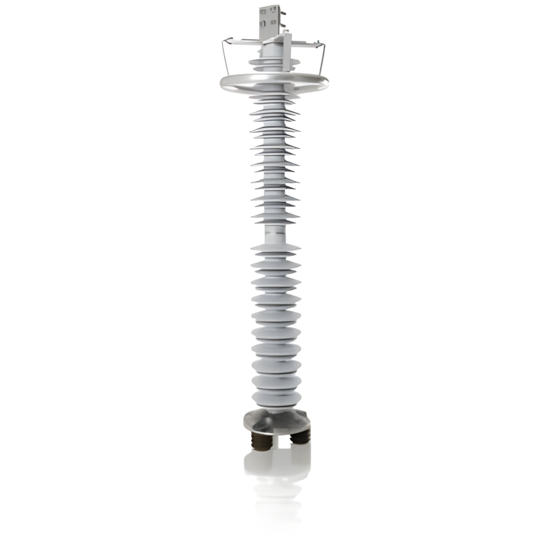
110 - 500kV Composite-Housed Line Surge Arresters
-
35 - 220kV Suspended Composite - Housed Metal Oxide Surge Arresters
-
500kV Series Porcelain-Housed Metal Oxide Surge Arresters
-
Underground Arresters
-
3 to 48kV Porcelain Housed Surge Arresters
-
3 to 550kV Station Class Metal-oxide surge arresters
-
30 to 52kV Outdoor Metal-oxide (MO) surge arrester
Related Knowledges
-
 Impact of DC Bias in Transformers at Renewable Energy Stations Near UHVDC Grounding ElectrodesImpact of DC Bias in Transformers at Renewable Energy Stations Near UHVDC Grounding ElectrodesWhen the grounding electrode of an Ultra-High-Voltage Direct Current (UHVDC) transmission system is located close to a renewable energy power station, the return current flowing through the earth can cause a rise in ground potential around the electrode area. This ground potential rise leads to a shift in the neutral-point potential of nearby power transformers, inducing DC bias (or DC offset) in their01/15/2026
 -
 HECI GCB for Generators – Fast SF6 Circuit Breaker1.Definition and Function1.1 Role of the Generator Circuit BreakerThe Generator Circuit Breaker (GCB) is a controllable disconnect point located between the generator and the step-up transformer, serving as an interface between the generator and the power grid. Its primary functions include isolating generator-side faults and enabling operational control during generator synchronization and grid connection. The operating principle of a GCB is not significantly different from that of a standard c01/06/2026
 -
 Distribution Equipment Transformer Testing, Inspection, and Maintenance1.Transformer Maintenance and Inspection Open the low-voltage (LV) circuit breaker of the transformer under maintenance, remove the control power fuse, and hang a “Do Not Close” warning sign on the switch handle. Open the high-voltage (HV) circuit breaker of the transformer under maintenance, close the grounding switch, fully discharge the transformer, lock the HV switchgear, and hang a “Do Not Close” warning sign on the switch handle. For dry-type transformer maintenance: first clean the porcel12/25/2025
 -
 How to Test Insulation Resistance of Distribution TransformersIn practical work, insulation resistance of distribution transformers is generally measured twice: the insulation resistance between thehigh-voltage (HV) windingand thelow-voltage (LV) winding plus the transformer tank, and the insulation resistance between theLV windingand theHV winding plus the transformer tank.If both measurements yield acceptable values, it indicates that the insulation among the HV winding, LV winding, and transformer tank is qualified. If either measurement fails, pairwise12/25/2025
 -
 Design Principles for Pole-Mounted Distribution TransformersDesign Principles for Pole-Mounted Distribution Transformers(1) Location and Layout PrinciplesPole-mounted transformer platforms should be located near the load center or close to critical loads, following the principle of “small capacity, multiple locations” to facilitate equipment replacement and maintenance. For residential power supply, three-phase transformers may be installed nearby based on current demand and future growth projections.(2) Capacity Selection for Three-Phase Pole-Mounted Tr12/25/2025
 -
 Transformer Noise Control Solutions for Different Installations1.Noise Mitigation for Ground-Level Independent Transformer RoomsMitigation Strategy:First, conduct a power-off inspection and maintenance of the transformer, including replacing aged insulating oil, checking and tightening all fasteners, and cleaning dust from the unit.Second, reinforce the transformer foundation or install vibration isolation devices—such as rubber pads or spring isolators—selected based on the severity of vibration.Finally, strengthen sound insulation at weak points of the ro12/25/2025
Related Solutions
-
 Distribution automation systems solutionsWhat are the difficulties in overhead line operation and maintenance?Difficulty one:Overhead lines of distribution network have wide coverage,complicatedterrain,many radiation branches and distributed power supply,resultingin "many line faults and difficulty in fault troubleshooting".Difficulty Two:Manual troubleshooting is time-consuming and laborious.Meanwhile,therunning current,voltage and switching state of the line cannot be graspedin real time,because of the lack of intelligent technical m04/22/2025
 -
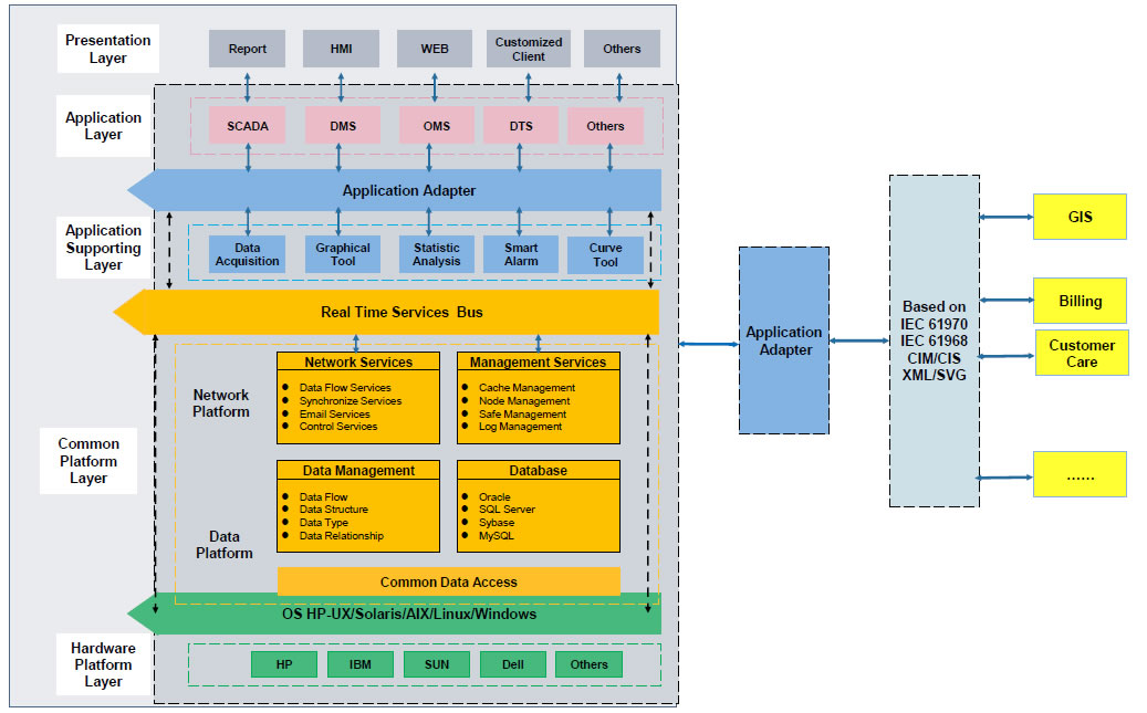 RW8000 DMS Distribution Management System SolutionsOverviewNowadays, the development trend of power grid is intellectualization. As an important part of power grid, the power distribution system is very close to the customers and it has to run properly. The distribution management system (DMS)played an important role in it.Introduction:RW8000 power distribution management system (DMS) is designed for the smart grids. It is based on real-time application, centered on distribution network operation and management, focusing on the business process09/07/2023
 -
 High-Precision Electrical Parameter Monitoring System Solution1.IntroductionWith the increasingly stringent requirements for power supply quality in high-end facilities such as precision manufacturing, medical diagnosis, and data centers, traditional power monitoring systems, due to their low sampling accuracy and weak data analysis capabilities, can no longer meet the demand for deep insight and precise management of power quality. In response, we are introducing a new generation High-Precision Electrical Parameter Monitoring System. With millisecond-l09/28/2025


