1 Research Background
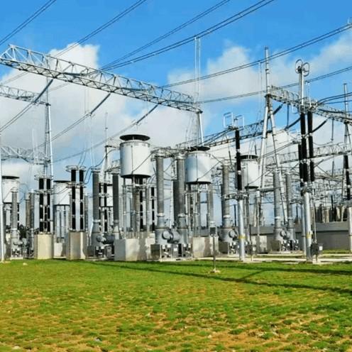
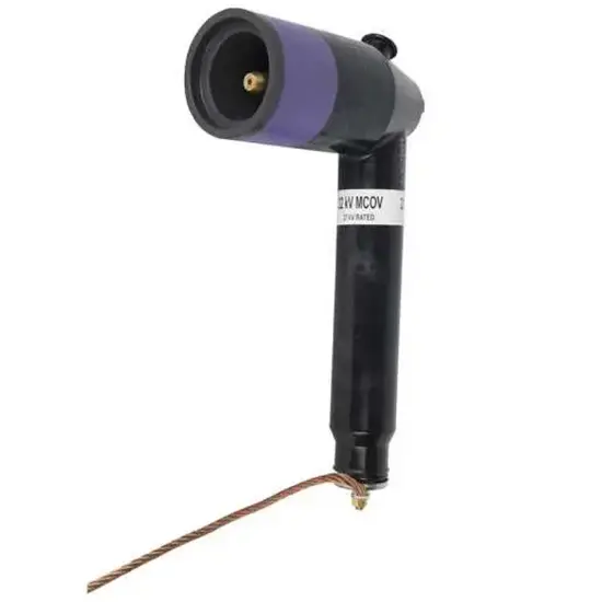
Metal - oxide surge arresters, sealed in cabinets, bear system voltage continuously, risking aging failures, even breakdowns/explosions causing electrical fires. Thus, regular inspection/maintenance is needed. Traditional 3–5 - year - cycle detection (power cut, arrester removal for tests; reinstallation if replaced) poses safety risks and faces space/environment - based standard - grasping difficulties.
2 Monitoring Principle of 10kV GIS Cabinet Surge Arrester
To ensure high - speed railway safety, enable real - time monitoring of 10kV GIS cabinet arrester status, judge service life, and timely replace expired ones, developing a monitoring system is imperative.
In normal GIS cabinet operation, arresters show high impedance; during grounding faults, they release energy then quickly restore high impedance to block ground current. Normally, leakage current (tens of mA, ~10mA resistive component) is tiny. Aging or moisture damage increases resistive leakage current, but minor issues cause unobvious increases, hindering timely hazard detection and threatening railway safety. Thus, resistive current analysis and methods (compensation, total leakage current, third - harmonic) are needed.
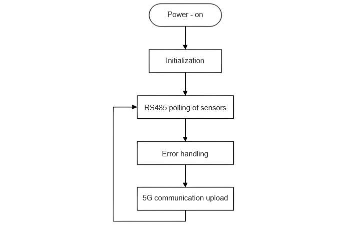
To boost safety, design a leakage - current - monitoring comprehensive unit (principle in Figure 1). It monitors multiple arresters online, tracking parameters like leakage current. Powered on, it initializes, cycles sensor checks, addresses errors promptly, and uploads data to servers via 5G for remote monitoring.
3 Implementation of the Monitoring System for Surge Arresters in GIS Cubicles of 10kV Substations
Guided by the monitoring principle, the system is designed and implemented. Each online surge arrester monitoring subsystem transmits data to the internal substation system. It can collect parameters including the number of arrester operations, leakage current, operation timestamps (accurate to the second), and peak discharge current during operations.
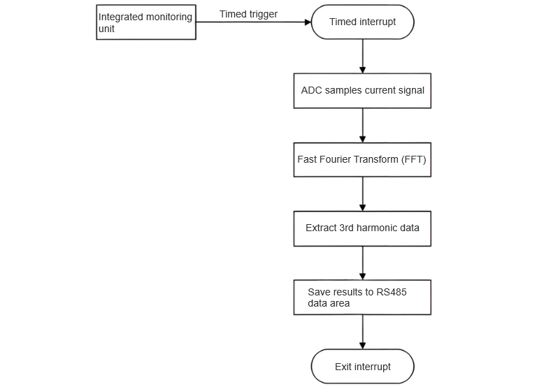
Surge arresters use through - core zero - flux leakage current sensors to acquire total current signals. These signals then undergo Fast Fourier Transform (FFT) – an efficient algorithm that reduces computational complexity while enabling rapid calculation of Fourier transforms and their inverses, making it an indispensable mathematical tool in power systems. FFT decomposes current signals to identify harmonic components and analyze frequency - based harmonics.
The GIS in 10kV substations suffers severe third - harmonic pollution, which increases system losses, elevates loads, and impairs arrester monitoring – threatening railway power system safety and stability. Thus, the system adopts the third - harmonic method: analyzing “third - harmonic” data (three times the 50Hz fundamental frequency) decomposed via FFT. The integrated monitoring unit connects to arrester sensors through RS485 interfaces, enabling data collection from up to 32 switchgear arresters.
3.1 Data Transmission and Smart Analysis
The integrated monitoring unit uses a 5G communication module to rapidly transmit detection data to the cloud platform. The platform analyzes arrester operation statuses, triggers alarms for anomalies, and periodically uploads data. Automated data analysis generates recommendations – e.g., timely arrester replacement or lifecycle predictions. The acquisition system supports scheduled data uploads and active uploads during anomalies (as shown in Figure 2).
3.2 System Operation and Management
Post - implementation, the unit processes total current, third - harmonic, and operation data to calculate total current, resistive current, and operation info – transmitted to the cloud via 5G. The cloud platform displays arrester lifecycle curves and action alarms, enabling real - time lifecycle and operation monitoring. Substation backend software stores all detection data, with configurable daily upload frequencies/timings. If leakage current exceeds 10% of the baseline, the system triggers alarms.
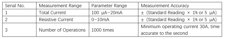
Key technical parameters are set as in Table 1. The monitoring system is installed and operational, with debugging aligned to equipment maintenance schedules. It achieves arrester lifecycle management, real - time monitoring, and improved maintenance efficiency – elevating power system management standards.
4 Conclusion
The real - time monitoring system for the operating status of surge arresters in GIS cubicles of 10kV substations transmits collected data to the backend monitoring system via 5G wireless transmission. Meanwhile, in the backend monitoring system, it generates curves of arrester lifespan changes and alarm notifications for arrester operations, enabling real - time grasp of arrester lifespan conditions and operation statuses.
The design and implementation of this system enhance the accuracy of operation monitoring for surge arresters in GIS cubicles of 10kV substations, reduce maintenance costs, and prevent major accidents. Additionally, it improves the power security for the operation of high - speed railways.