| Brand | RW Energy |
| Model NO. | APView500 power analyzer with ModBus-RTU communication protocol |
| Rated frequency | 50/60Hz |
| Series | APView |
General
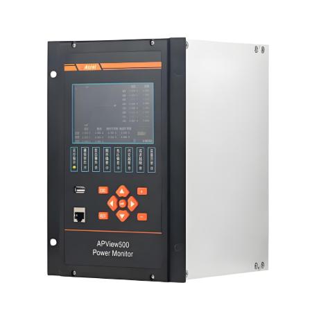
Power quality monitor APView500 integrates a high-performance multi-core platform and an embedded operating system, and monitors power quality indexes stipulated in IEC61000-4-30 Testing and measurement techniques –Power quality measurement methods, and provides various functions such as harmonic analysis, waveform sampling, voltage dips/swells/interruptions monitoring, flicker monitoring , voltage unbalance monitoring, event recording and measurement control. It meets IEC 61000-4-30 Class A Edition 3.1 with respect to standardization of power quality index measurement methods, measurement accuracy of index parameters, clock synchronization, event alarms and others and satisfy the demands of power quality monitoring of power supply system up to 110kV. Therefore, it is widely applicable for power quality monitoring in chemical industry, steel industry, metallurgy industry, hospitals, data centers, transportation, construction industry and other industries.
Parameters
Technical Datasheet
|
Technical Parameter |
Value |
|
Rated Value |
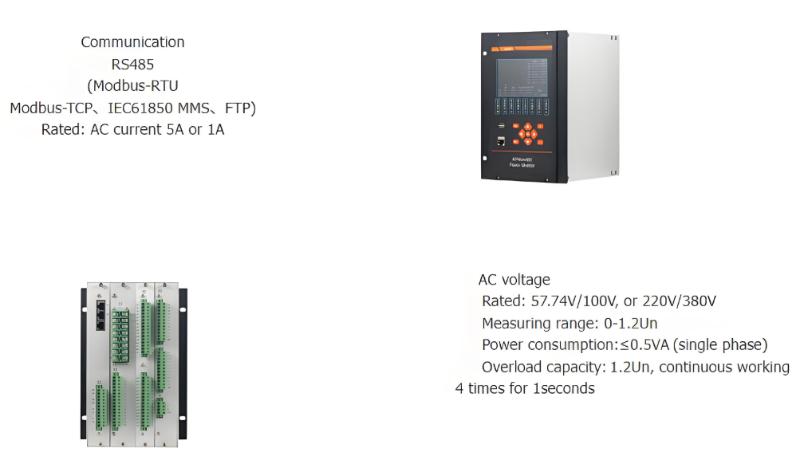
AC voltage:AC/DC220V, AC/DC110V or DC48V AC current:AC1A,5A; |
|
Overload capacity |
1.2In, continuous working 20 times for 1 second
|
|
power supply |
Rated: AC/DC220, AC/DC110V or DC48V Permissible deviation: -20%-+20% Power consumption:≤15W |
|
Power Consumption |
≤0.5VA (single phase) |
|
Measuring rage |
0-1.2In |
|
Digital output |
Mechanical service life: ≥10000 Output mode: Passive contacts Switching capacity: ≤4000W or ≤384VA On-state current: ≥16A(AC250V/DC24V) in the continuous mode; ≥30A for a short term (200ms)
|
|
Accuracy |
Class 0.5 |
|
RMS Voltage:±0.1% RMS Current:±0.1% P,Q,S:±0.2% Power factor:Class 0.5 Voltage deviation:0.1% Frequency deviation:±0.001Hz
|
|
|
Communication |
RS485,Modbus-RTU protocol;Ethernet. |
|
Three phase unbalance |
Voltage unbalance:±0.15% Current unbalance:±1% |
|
Power frequency withstand voltage |
Between power supply set of terminals and signal input,output set of terminals 2kV/1min (RMS) Between the shell and all set of terminals(except the set of terminals reference voltage less than 40V) AC 4kV |
|
Temperature |
Operation: -10℃~+55℃Storage: -30℃-+80℃ |
|
Humidity |
≤95%RH,no condensation,without corrosive gas |
|
Altitude |
≤ 2500m |
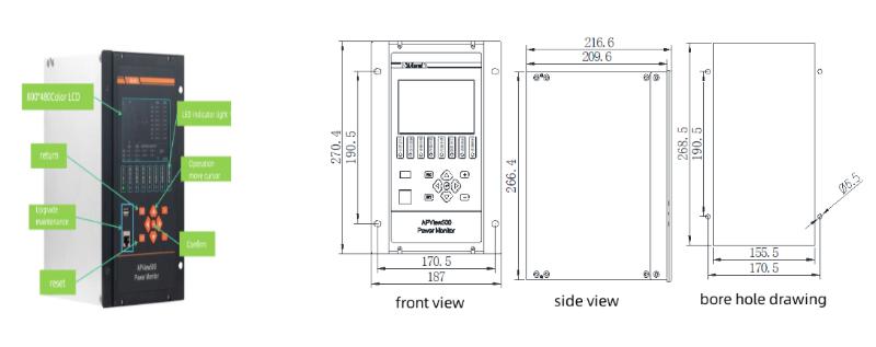
Dimension
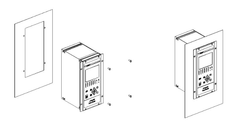
Installation
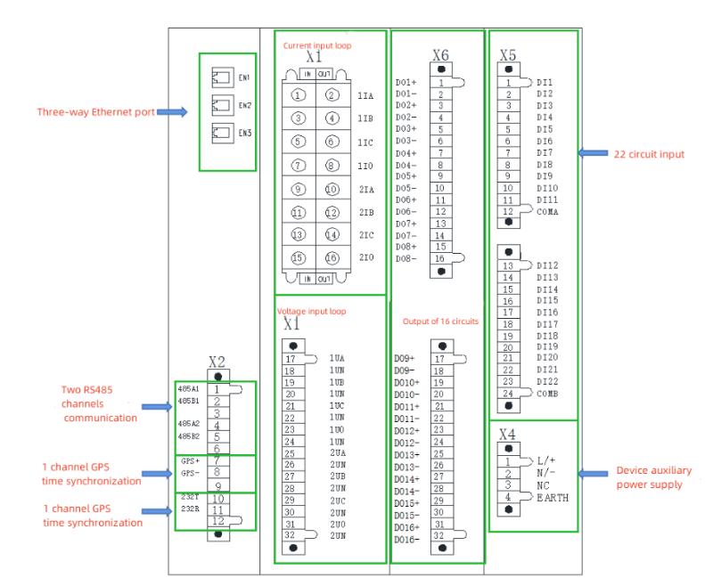
Wiring
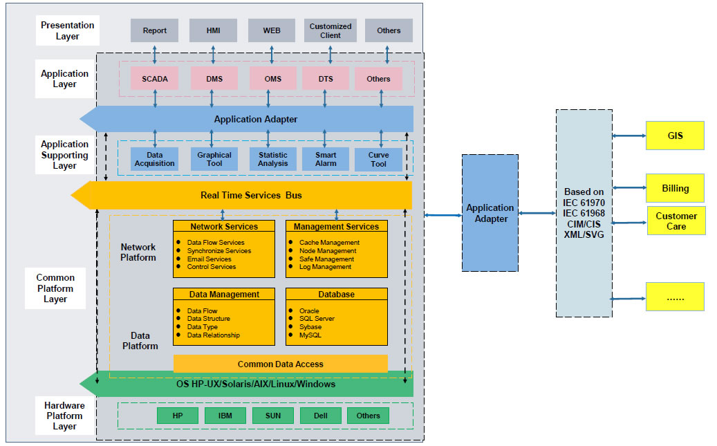
Network
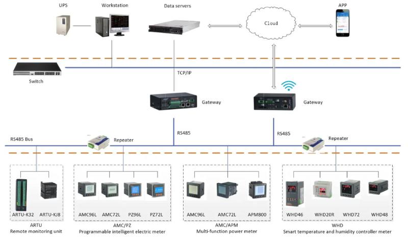
RS485 Modbus RTU and Ethernet communication, directly connected to a computer or PLC. The supporting software allows real-time viewing of waveforms, recording of data, and generation of reports. No need to dismantle equipment, remote monitoring is extremely convenient, and it is the preferred choice for large enterprises.
All three-phase four wire or three-phase three wire can be measured, and the A/B/C three-phase parameters are clear at a glance. Being able to analyze imbalance, I am an expert in "power health checks" for factories and data centers, and can handle comprehensive monitoring with just one meter.
Compliant with IEC 61000-4-30 Class A standard, voltage/current accuracy ± 0.1%, power ± 0.2%. Being able to analyze harmonics, voltage dips, and flicker, with data accurate to three decimal places, is the "gold standard" for power quality monitoring.