| Brand | Wone Store |
| Model NO. | 38/66kV 220/400kV High and Extra High Voltage Cables |
| Rated voltage | 38/66kV |
| Rated frequency | 50/60Hz |
| Series | YJV |
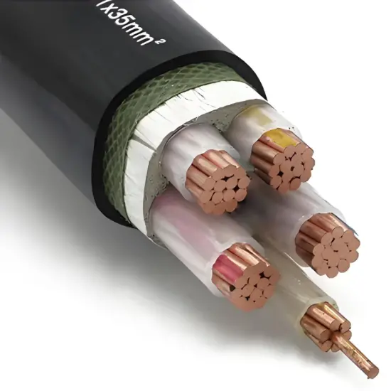
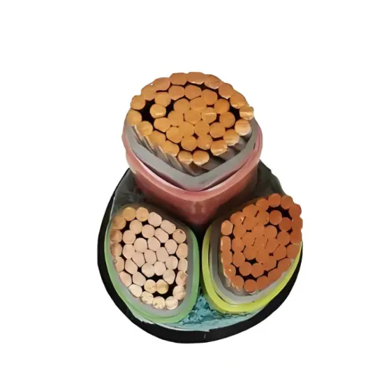
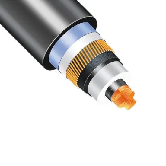
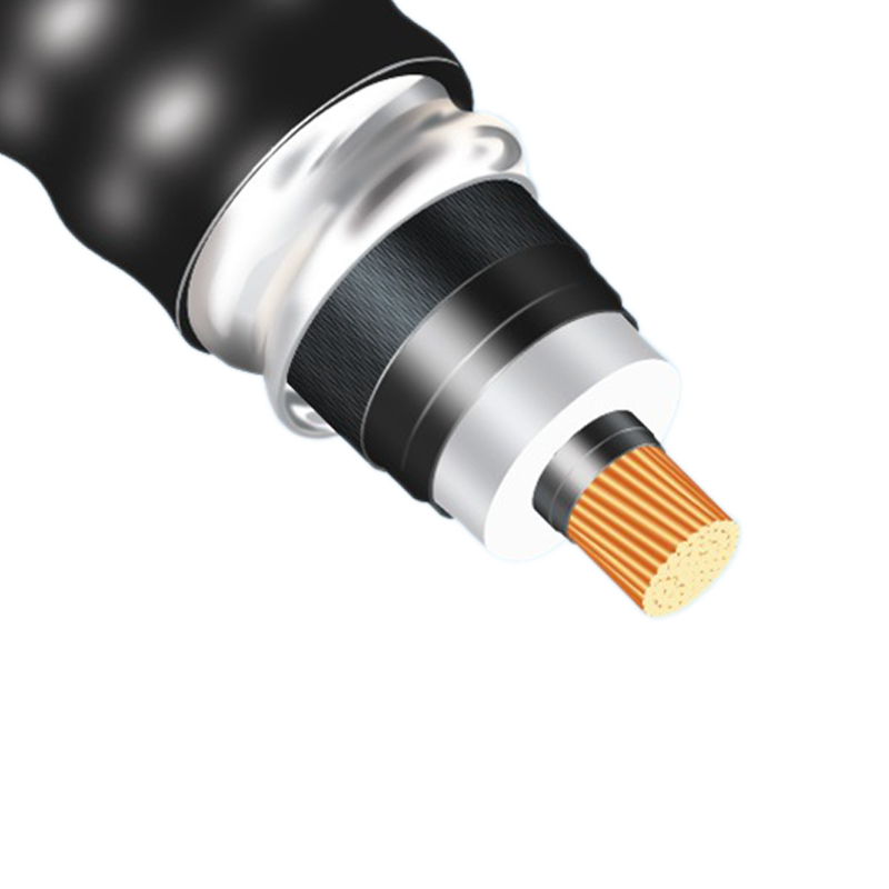
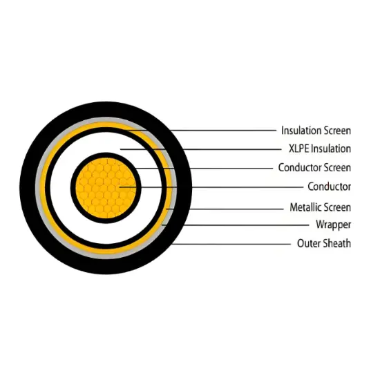
38/66kV high and extra-high voltage cables serve as core carriers in power systems, primarily connecting substations, transmission lines, and end-users. They are mainly used for medium- and long-distance high-voltage power transmission and connecting equipment within substations. Adopting a multi-layer composite structure comprising a cross-linked polyethylene (XLPE) insulation layer, metal shielding layer, and flame-retardant outer sheath, these cables optimize conductor materials (e.g., high-purity electrolytic copper) and insulation formulations to enable stable operation under 38kV/66kV high-voltage conditions. Widely applied in scenarios such as urban power grid trunk lines, grid connection of new energy power stations (photovoltaic/wind power), and high-voltage power distribution in industrial parks, they are critical infrastructure ensuring safe and efficient transmission of high-voltage power.
Precise Adaptation to Medium and High-Voltage Transmission Scenarios with Strong Voltage Compatibility:The rated voltage of 38/66kV covers the core range of high-voltage power grids. It can not only meet the upgrading needs of 35kV distribution networks but also satisfy 66kV regional transmission projects (such as main power supply for industrial parks and interconnection of urban outer-ring power grids). There is no need to replace cables due to voltage fluctuations, and its adaptability is far superior to products with a single voltage level.
Multi-Scenario Installation Adaptation with Excellent Environmental Interference Resistance:Supports various installation methods including direct burial, pipe threading, tunneling, and overhead installation (requires matching overhead accessories). The sheath can be optionally made of polyvinyl chloride (PVC, acid and alkali resistant) or polyethylene (PE, strong weather resistance). Armored versions (such as steel tape armored YJV22 type) can resist soil extrusion and rodent/insect bites. The operating temperature range covers -40℃ to +50℃, ensuring normal operation in alpine and high-humidity areas (such as southern plum rain regions and northern frigid regions).
Optional Flame Retardant/Low Smoke Zero Halogen with Flexible Safety Protection Levels:The basic model meets the requirements of GB/T 18380 flame retardant Class B, with only local combustion and self-extinguishing in case of fire. For special scenarios such as subways, hospitals, and data centers, a low smoke zero halogen (LSZH) version can be customized, which produces smoke density ≤100 (minimum light transmittance ≥70%) during combustion without toxic gas emission, meeting the upgraded fire safety requirements.
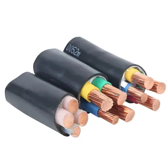
High-Conductivity Conductors + Low-Loss Design with Significant Energy Efficiency Advantages:Conductors are made of high-purity electrolytic copper (T2) or AA8030 aluminum alloy, with conductivity of ≥97% and ≥61% respectively (IACS standard), and low current skin effect. After structural optimization (such as compacted round conductors), the DC resistance is 5%-8% lower than ordinary cables, reducing power loss during long-term operation, making it particularly suitable for long-distance (e.g., 10-20km) transmission projects.
Parameters
Core Count |
Conductor |
Voltage |
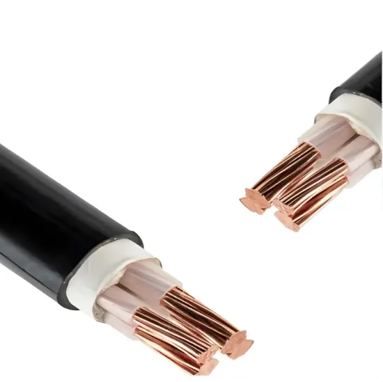
Single Core |
Copper |
38/66kV |
76/132kV |
||
87/150kV |
||
127/220kV |
||
160/275kV |
||
190/330kV |
||
220/400kV |
||
290/500kV |
||
Aluminium |
38/66kV |
|
76/132kV |
||
87/150kV |
||
127/220kV |
||
160/275kV |
||
190/330kV |
||
220/400kV |
||
290/500kV |
Structural Parameters

Electrical Characteristics

Current Ratings

Rated voltage |
38/66kV |
Max. operating temperature of conductor |
90℃ |
Max. short - circuit operation temperature of conductor (5s Max. duration) |
250℃ |
Ambient temperature range for operating |
from - 40℃ to + 50℃ |
Relative air humidity at temperature lower than + 35℃ |
up to 95% |
Min. temperature for installing without preheating |
+ 0℃ |
Standard |
AS/NZS 1429.2 |
Fault Level |
as per customer requirements |