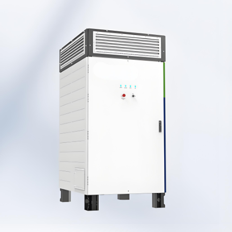
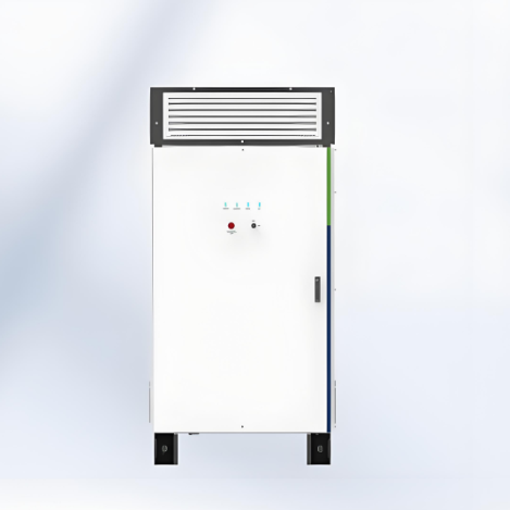
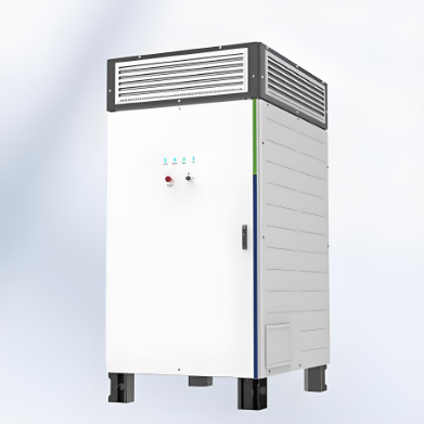
1725 KVA 2000KVA Power Conversion System (Central PCS)
Key attributes
| Brand | Wone |
| Model NO. | 1725 KVA Power Conversion System (Central PCS) |
| Max.Efficiency | 99% |
| AC output power | 1725kVA |
| Max. DC voltage | 1500V |
| Max. DC current | 1936A |
| Max. AC output current | 1046A |
| Series | Power Conversion System |
Product descriptions from the supplier
Features
Max. efficiency up to 99%.
Full reactive power four-quadrant capability.
IP65 protection degree.
Black start ability.
Support VSG function.
Millisecond-level Power response to EMS/SCADA.
Three level topology.
Use alone or in combination with MV station.
DC Parameters:

AC parameters (On-Grid):

AC parameters (Off-Grid):

General data:

How the energy storage converter is short-circuit protected?
Current Detection
Function: Monitor the input and output currents of the converter in real time.
Principle: Use current sensors (such as Hall effect sensors, shunts, etc.) to detect the current. When a sudden increase in the current is detected and it exceeds the preset threshold, the system will determine that a short circuit may have occurred.
Overcurrent Protection
Function: Quickly cut off the power supply when an overcurrent is detected to prevent the short circuit from developing further.
Principle:Hardware Protection: Use hardware devices such as fast fuses, circuit breakers, or MOSFETs (Metal Oxide Semiconductor Field Effect Transistors) to cut off the current.
Software Protection: Execute the protection logic through a microprocessor or controller to control relays or MOSFETs to cut off the current.
Protection Measures
Cutting off the Power Supply: Cut off the power supply through relays or MOSFETs to prevent the short-circuit current from continuing to flow.
Alarm Notification: Issue an alarm through the display screen or indicator lights to remind the user that there is a short-circuit fault in the system.
Fault Isolation: When a short circuit is detected, isolate the faulty part to prevent the fault from spreading to other parts.

Related Products
-
LFP All-in-One Energy Storage Battery with Inverter & Controller
-
5.12kWh low-voltage wall-mounted lithium battery
-
5-20 kWh AC/ DC / Hybrid-Coupling residential energy storage system
-
Class-A 5.12KWh Low Voltage Energy Storage Battery for Energy Storage System
-
4.8kWh 5.12kWh Commercial Use Stacked energy storage battery
-
9.6KWh/10.24KWh Household Column energy storage battery
-
2.4–10.24 KWh Household Wall - Mounted Energy Storage Battery
Related Knowledges
-
 Main Transformer Accidents and Light Gas Operation Issues1. Accident Record (March 19, 2019)At 16:13 on March 19, 2019, the monitoring background reported a light gas action of No. 3 main transformer. In accordance with the Code for Operation of Power Transformers (DL/T572-2010), operation and maintenance (O&M) personnel inspected the on-site condition of No. 3 main transformer.On-site confirmation: The WBH non-electrical protection panel of No. 3 main transformer reported a Phase B light gas action of the transformer body, and the reset was ineff02/05/2026
 -
 Faults and Handling of Single-phase Grounding in 10kV Distribution LinesCharacteristics and Detection Devices for Single-Phase Ground Faults1. Characteristics of Single-Phase Ground FaultsCentral Alarm Signals:The warning bell rings, and the indicator lamp labeled “Ground Fault on [X] kV Bus Section [Y]” illuminates. In systems with a Petersen coil (arc suppression coil) grounding the neutral point, the “Petersen Coil Operated” indicator also lights up.Insulation Monitoring Voltmeter Indications:The voltage of the faulted phase decreases (in01/30/2026
 -
 Neutral point grounding operation mode for 110kV~220kV power grid transformersThe arrangement of neutral point grounding operation modes for 110kV~220kV power grid transformers shall meet the insulation withstand requirements of transformer neutral points, and shall also strive to keep the zero-sequence impedance of substations basically unchanged, while ensuring that the zero-sequence comprehensive impedance at any short-circuit point in the system does not exceed three times the positive-sequence comprehensive impedance.For 220kV and 110kV transformers in new constructi01/29/2026
 -
 Why Do Substations Use Stones, Gravel, Pebbles, and Crushed Rock?Why Do Substations Use Stones, Gravel, Pebbles, and Crushed Rock?In substations, equipment such as power and distribution transformers, transmission lines, voltage transformers, current transformers, and disconnect switches all require grounding. Beyond grounding, we will now explore in depth why gravel and crushed stone are commonly used in substations. Though they appear ordinary, these stones play a critical safety and functional role.In substation grounding design—especially when multiple gr01/29/2026
 -
 Why Must a Transformer Core Be Grounded at Only One Point? Isn't Multi-Point Grounding More Reliable?Why Does the Transformer Core Need to Be Grounded?During operation, the transformer core, along with the metal structures, parts, and components that fix the core and windings, are all situated in a strong electric field. Under the influence of this electric field, they acquire a relatively high potential with respect to ground. If the core is not grounded, a potential difference will exist between the core and the grounded clamping structures and tank, which may lead to intermittent discharge.I01/29/2026
 -
 Understanding Transformer Neutral GroundingI. What is a Neutral Point?In transformers and generators, the neutral point is a specific point in the winding where the absolute voltage between this point and each external terminal is equal. In the diagram below, pointOrepresents the neutral point.II. Why Does the Neutral Point Need Grounding?The electrical connection method between the neutral point and earth in a three-phase AC power system is called theneutral grounding method. This grounding method directly affects:The safety, reliabilit01/29/2026


