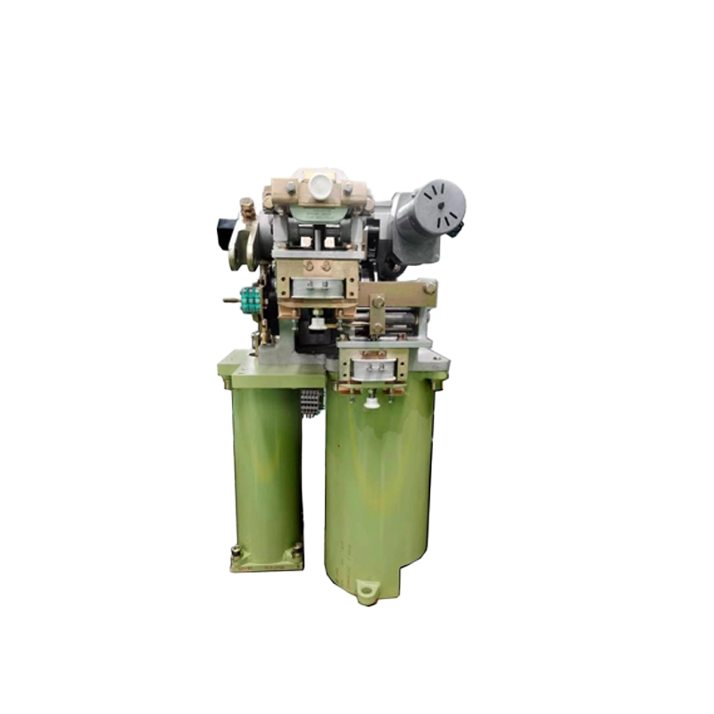
110kV CT126-1 Circuit Breaker Spring Operating Mechanism
Key attributes
| Brand | Switchgear parts |
| Model NO. | 110kV CT126-1 Circuit Breaker Spring Operating Mechanism |
| Rated voltage | 110kV |
| Rated frequency | 50/60Hz |
| Series | CT126-1 |
Product descriptions from the supplier
The 110kV CT126-1 porcelain column SF6 gas circuit breaker is the "safety gate" of high-voltage distribution networks. Its dedicated spring operated mechanism serves as the core power component, with "high-voltage adaptation, high reliability, and fast response" as the design core. Through customized energy storage and transmission systems, it accurately matches the opening and closing requirements of the circuit breaker, and is widely used in 110kV substations, cross regional transmission lines, and large industrial high-voltage distribution systems to ensure reliable on/off and fault isolation of high-voltage circuits.
1、 Core Working Principle: Energy Storage Transmission Logic in High Voltage Scenarios
1. Customized dual spring energy storage system
In response to the high operating power demand of 110kV circuit breakers (closing operation power ≥ 450J), the mechanism adopts a dual spring combination design of "main closing spring+auxiliary energy storage spring":
Main spring: Made of 60Si2MnA high-strength alloy spring steel with a diameter of 28mm, quenched at 1050 ℃ and tempered at 450 ℃, the tensile strength reaches 2100MPa, and can store 520J of energy at a maximum deformation of 35mm, providing core power for closing action;
Auxiliary spring: Made of φ 12mm 50CrVA spring steel, compressed synchronously with the main spring to assist in load sharing, reduce fatigue loss of the main spring, and extend the overall spring component life (≥ 15000 energy storage cycles).
The energy storage method supports dual modes of "electric+manual" and is suitable for emergency needs in high-voltage scenarios
Electric energy storage: Equipped with a 2.2kW three-phase asynchronous motor (AC380V, speed 1450r/min), the energy storage shaft is driven to rotate through three-stage helical gear reduction (reduction ratio 1:150), and the cam mechanism pushes the spring to compress. After the energy storage is completed, it is mechanically locked by the double pawl, and the travel switch triggers the motor to cut off power. The whole process takes ≤ 25s
Manual energy storage: In emergency situations, insert a Z-shaped extended rocker handle (650mm in length, designed with a labor-saving lever). When the rocker handle rotates at 20r/min, energy storage can be completed within ≤ 60 turns, meeting the emergency operation needs during power outages
2. Coordination of high-voltage opening and closing actions
The transmission connection between the mechanism and CT126-1 circuit breaker has been precisely calibrated to ensure precise operation in high-voltage scenarios
Closing process: After receiving the closing signal, the DC220V closing electromagnet (suction force ≥ 90N) pushes the release pin, and the double claws are synchronously released. The main spring instantly releases energy, and the main shaft of the circuit breaker is driven to rotate through the chrome molybdenum steel transmission connecting rod (φ 20mm, yield strength ≥ 800MPa), and the moving contact quickly closes. The closing time is ≤ 80ms, ensuring the rapid restoration of power supply to the 110kV line; At the same time, the opening spring synchronously stretches and stores energy, and the pre tightening force can be fine tuned within the range of 50-80N by adjusting the nut, adapting to the opening speed requirements of different arc extinguishing chambers.
Opening process: When the system detects faults such as short circuit (short circuit current ≤ 40kA), overload, etc., the opening electromagnet (or manual opening handle) will act, the opening lock will release, the opening spring will release energy, and the transmission mechanism will drive the moving contact to open. The opening time is ≤ 30ms, and it will cooperate with the arc extinguishing chamber of the circuit breaker to quickly cut off the high-voltage arc, avoiding the expansion of the fault. The opening rebound amount is ≤ 2mm, which meets the requirements of GB/T 1984-2014 "High Voltage AC Circuit Breaker" standard.

Related Products
-
160-250A DNH40 Series Disconnector Switch

-
315-400A DNH40 Series Disconnector Switch

-
3200-4000A DNH40 series isolator switches

-
2000-2500A DNH40 Series Disconnector Switch

-
630-800A DNH40 Series Disconnector Switch

-
HH15 series Disconnector fuse group and disconnector

-
Disconnector Fuse Group HGLR Series, Fuse Switch Disconnector

Related Knowledges
-
 Main Transformer Accidents and Light Gas Operation Issues1. Accident Record (March 19, 2019)At 16:13 on March 19, 2019, the monitoring background reported a light gas action of No. 3 main transformer. In accordance with the Code for Operation of Power Transformers (DL/T572-2010), operation and maintenance (O&M) personnel inspected the on-site condition of No. 3 main transformer.On-site confirmation: The WBH non-electrical protection panel of No. 3 main transformer reported a Phase B light gas action of the transformer body, and the reset was ineff02/05/2026
 -
 Faults and Handling of Single-phase Grounding in 10kV Distribution LinesCharacteristics and Detection Devices for Single-Phase Ground Faults1. Characteristics of Single-Phase Ground FaultsCentral Alarm Signals:The warning bell rings, and the indicator lamp labeled “Ground Fault on [X] kV Bus Section [Y]” illuminates. In systems with a Petersen coil (arc suppression coil) grounding the neutral point, the “Petersen Coil Operated” indicator also lights up.Insulation Monitoring Voltmeter Indications:The voltage of the faulted phase decreases (in01/30/2026
 -
 Neutral point grounding operation mode for 110kV~220kV power grid transformersThe arrangement of neutral point grounding operation modes for 110kV~220kV power grid transformers shall meet the insulation withstand requirements of transformer neutral points, and shall also strive to keep the zero-sequence impedance of substations basically unchanged, while ensuring that the zero-sequence comprehensive impedance at any short-circuit point in the system does not exceed three times the positive-sequence comprehensive impedance.For 220kV and 110kV transformers in new constructi01/29/2026
 -
 Why Do Substations Use Stones, Gravel, Pebbles, and Crushed Rock?Why Do Substations Use Stones, Gravel, Pebbles, and Crushed Rock?In substations, equipment such as power and distribution transformers, transmission lines, voltage transformers, current transformers, and disconnect switches all require grounding. Beyond grounding, we will now explore in depth why gravel and crushed stone are commonly used in substations. Though they appear ordinary, these stones play a critical safety and functional role.In substation grounding design—especially when multiple gr01/29/2026
 -
 Why Must a Transformer Core Be Grounded at Only One Point? Isn't Multi-Point Grounding More Reliable?Why Does the Transformer Core Need to Be Grounded?During operation, the transformer core, along with the metal structures, parts, and components that fix the core and windings, are all situated in a strong electric field. Under the influence of this electric field, they acquire a relatively high potential with respect to ground. If the core is not grounded, a potential difference will exist between the core and the grounded clamping structures and tank, which may lead to intermittent discharge.I01/29/2026
 -
 Understanding Transformer Neutral GroundingI. What is a Neutral Point?In transformers and generators, the neutral point is a specific point in the winding where the absolute voltage between this point and each external terminal is equal. In the diagram below, pointOrepresents the neutral point.II. Why Does the Neutral Point Need Grounding?The electrical connection method between the neutral point and earth in a three-phase AC power system is called theneutral grounding method. This grounding method directly affects:The safety, reliabilit01/29/2026


