How does the TTC series dry-type transformer temperature controller prevent transformer overheating?

1. Function of Transformer Temperature Controllers
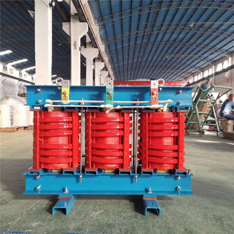
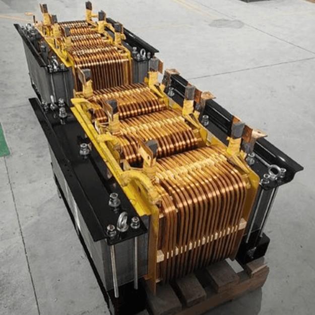
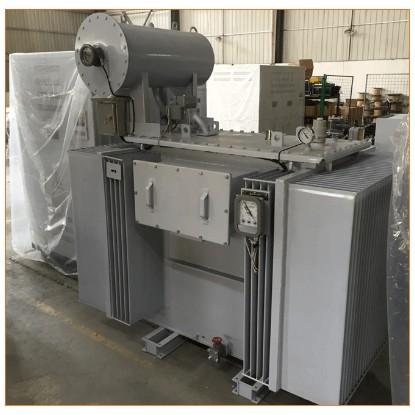
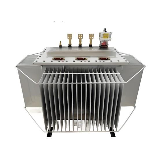
Today, power transformers are primarily categorized into two types: oil-immersed and dry-type transformers. Dry-type transformers are widely used in power plants, substations, airports, railways, intelligent buildings, and smart residential communities due to their numerous advantages—such as inherent safety, flame resistance, zero pollution, maintenance-free operation, low losses, minimal partial discharge, and long service life.
A key advantage of dry-type transformers is their design life, typically exceeding 20 years. The longer the operational lifespan, the lower the total cost of ownership. In practice, the safe operation and longevity of a dry-type transformer largely depend on the reliability of its windings. One of the primary causes of transformer failure is insulation degradation resulting from winding temperatures exceeding the thermal endurance limit of the insulation material.
Moreover, the service life of a dry-type transformer is generally limited by its "thermal life." To maximize operational life, it is essential to monitor winding temperature using a temperature control system and implement timely protective measures—such as forced cooling or alarm warnings—when necessary.
2. Types of Transformer Temperature Controllers
2.1 By Temperature Sensing Method: Mechanical vs. Electronic
Mechanical temperature controllers are typically expansion-type devices that use an oil-filled bulb as the sensing element, operating on the principle of thermal expansion and contraction. Due to their bulky oil bulb and inconvenient installation, they are generally used only on oil-immersed transformers.
Electronic temperature controllers employ temperature sensors such as resistance temperature detectors (e.g., Pt100, PTC) or thermocouples. Thanks to their high technological sophistication, comprehensive functionality, high accuracy, and user-friendly operation, electronic controllers are now widely applied in both oil-immersed and dry-type transformers.
2.2 By Installation Method: Embedded vs. External-Mounted
Embedded controllers are directly mounted on the transformer clamping frame (for units without enclosures) or integrated into the transformer’s enclosure.
External-mounted (wall-mounted) controllers are installed on walls (for non-enclosed units) or affixed to the outer surface of the transformer enclosure.
Dry-type transformers generate significant heat, low-frequency vibration, and electromagnetic interference during operation—conditions that severely impact embedded temperature controllers installed on clamping frames or within enclosures.
It is well known that electronic components, like dry-type transformers themselves, have a finite "thermal life." The embedded installation method significantly reduces the controller’s service life and reliability. In contrast, external-mounted controllers are effectively isolated from this harsh environment, ensuring better protection and longevity.
3.TTC Series Dry-Type Transformer Temperature Controller
JB/T 7631-94 “Resistance Thermometers for Transformers” is a standard issued by China’s Ministry of Mechanical Industry in 1994, specifically for temperature indicators and controllers used with dry-type transformers. It incorporates requirements from GB/T 13926-92 “Electromagnetic Compatibility for Industrial Process Measurement and Control Equipment.”
The TTC series temperature controllers comply with the updated standard GB/T 17626-1998 “Electromagnetic Compatibility – Testing and Measurement Techniques” (equivalent to IEC 61000-4:1995).
3.1 Working Principle
3.1 Circuit Block Diagram & Temperature Sensing Principles (Pt100 and PTC)
The Pt100 temperature sensor operates on the principle that its electrical resistance changes approximately linearly with ambient temperature. As shown in the resistance–temperature curve (right), the resistance of a Pt100 platinum resistor increases steadily and nearly linearly as temperature rises.
The temperature controller leverages this characteristic to provide continuous, accurate temperature monitoring of the transformer. The displayed temperature value is derived directly from measurements taken by the Pt100 sensor.
Due to its excellent repeatability and one-to-one correspondence between resistance and temperature, the Pt100 enables precise point-by-point temperature measurement, typically achieving an accuracy class of 0.5.

3.2 Ensuring Pt100 Temperature Measurement Accuracy
The Pt100 temperature sensor can be wired in two-wire, three-wire, or four-wire configurations. In most industrial temperature control applications, the three-wire connection is used because it effectively compensates for measurement errors caused by lead wire resistance.
For example: the amplifier circuit is typically a Wheatstone bridge. During manufacturing and calibration, shorting links are used for adjustment. However, in real-world operation, when sensor cables are connected, their inherent resistance introduces measurement errors. The three-wire configuration minimizes this error by balancing the bridge circuit.
Although the Pt100 resistance–temperature curve is nearly linear, it is not perfectly linear. To enhance accuracy, our temperature controllers divide the 0–200°C Pt100 resistance–temperature curve into five segments. Within each segment, a straight line is used to approximate the actual curve through linear fitting, significantly improving overall measurement precision.
3.3 PTC Thermistor as an Alternative Sensor in TTC-300 Series Controllers
The PTC (Positive Temperature Coefficient) thermistor is another temperature sensor used in our TTC-300 series transformer temperature controllers. PTC thermistors are made from barium titanate-based polycrystalline ceramic materials, doped to achieve specific "trip" or "switching" temperatures.
Unlike platinum resistors (Pt100), PTC thermistors exhibit a distinct nonlinear behavior: their resistance remains relatively stable at lower temperatures but undergoes a sharp, almost step-like increase once the temperature reaches a predefined threshold—known as the Curie point or action temperature. This characteristic is illustrated in the resistance–temperature curve below.
As shown, below the action temperature, the PTC resistance changes little with temperature. However, when the temperature approaches and exceeds this critical point, the resistance surges dramatically—often by several orders of magnitude.
The operating principle of PTC-based temperature detection is to detect this abrupt resistance change to determine whether a specific temperature threshold has been reached. Consequently, PTC sensors can only indicate a single temperature point—they cannot provide continuous, full-range temperature measurements like Pt100.
Our products leverage this on/off characteristic of PTC sensors to implement over-temperature alarms and trip protection for transformers. To ensure product consistency, reliability, and high quality, we use PTC components sourced from Siemens–Matsushita Electronic Components Co., Ltd.

3.4 TC Temperature Sensing Principle
The temperature controller acquires temperature signals from both PTC and Pt100 sensors via its internal circuitry and uses logical judgment to determine whether to trigger an over-temperature alarm or an over-temperature trip signal. This dual-protection mechanism effectively prevents failures to act or false triggering.
Temperatures of the transformer windings (Phases A, B, C) and core (D) are monitored using Pt100 and PTC sensors. As temperature changes, the resistance of these sensors changes accordingly. The controller converts this resistance into a voltage signal, which is then processed through filtering, analog-to-digital (A/D) conversion, and advanced algorithms to calculate the corresponding temperature value.
Based on these two types of temperature inputs:
The controller displays the channel number and real-time temperature value on the front-panel screen.
Simultaneously, it applies logical algorithms to compare the measured temperature against user-defined setpoints. If the temperature exceeds the threshold, the controller activates appropriate outputs—such as starting/stopping cooling fans, triggering alarms, or initiating a trip command.
Users can configure system parameters—including fan start/stop temperatures, core overheat alarm thresholds, and other settings—via the front-panel buttons.
Additionally, the system continuously performs self-diagnostics. In the event of a sensor failure or internal hardware fault within the temperature controller, it immediately issues audible and visual alarms along with a fault signal to alert operators.