Electrical Fuse
In the normal working condition of the electrical network, the current flowing through the network is within the rated limit. If a fault occurs in the network mainly phase to phase short circuit fault or phase to ground fault, the network current crosses the rated limits.
This high current may have a very high thermal effect which will cause permanent damage to the valuable pieces of equipment connected to the electrical network. So this high fault current should be interrupted as fast as possible. This is what an electrical fuse does.
A fuse is a part of the circuit which consists of a conductor which melts easily and breaks the connection when the current exceeds the predetermined value. An electrical fuse is the weakest part of an electrical circuit that breaks when more than predetermined current flows through it.
The function of fuse wire is to carry the normal current without excessive heating but more than normal current when passes through fuse wire, it rapidly heats up and melts.
The materials used for fuse wires are mainly tin, lead, zinc, silver, antimony, copper, aluminum etc.
The melting point and specific resistance of different metals used for fuse wire
Metal |
Melting point |
Specific Resistance |
Aluminum |
240oF |
2.86 μ Ω – cm |
Copper |
2000oF |
1.72 μ Ω – cm |
Lead |
624oF |
21.0 μ Ω – cm |
Silver |
1830oF |
1.64 μ Ω – cm |
Tin |
463oF |
11.3 μ Ω – cm |
Zinc |
787oF |
6.1 μ Ω – cm |
It is already defined earlier.
It is also defined earlier.
It is the minimum value of current due to which fuse melts.
It is the maximum value of current due to which fuse does not get melt.
This is the ratio of minimum fusing current and current rating of the fuse.
Therefore, fusing factor = Minimum fusing current or current rating of the fuse.
The value of the fusing factor is always more than 1.
Before melting, the fuse element has to carry the short circuit current through it. The prospective current is defined as the value of current which would flow through the fuse immediately after a short circuit occurs in the network.
This is the time taken by a fuse wire to get broken by melting. It gets counted from the instant; the overcurrent starts flowing through the fuse, to the instant when the fuse wire gets just broken by melting.
After breaking of fuse wire there will be an arcing between both melted tips of the wire which will be extinguished at the current zero. The time accounted from the instant of arc initiated to the instant of the arc gets extinguished is known as arcing time of fuse.
Whenever overrated current starts to flow through a fuse wire, it takes time to be melted and disconnected, and just after that the arcing stars between the melted tips of the fuse wire, which finally gets extinguished. The operating time of the fuse is the time gap between the instant when the overrated current starts to flow through the fuse and the instant when the arc in the fuse finally gets extinguished. That means operating time of fuse = melting time + arcing time.
The current carrying capacity of a fuse wire depends upon a number of factors like, what material used for it, what are the dimension of it, i.e., diameter and length, size, and shape of terminals used to connect it, and the surrounding.
Fuse law determines the current carrying capacity of a fuse wire. We can establish the law in the following way.
At steady-state condition that is when fuse carries normal current without increasing its temperature to the melting limit. That means at this steady-state condition, the heat generated due to the current through fuse wire is equal to heat dissipated from it.
Heat generated = I2R.
Where R is the resistance of the fuse wire. Where, ρ is the resistivity, l is the length and a is the cross-sectional area of fuse wire.
 Where, d is the diameter of fuse wire.
 Where, K1 is a constant.
Heat lost ∝ surface area of fuse wire ∝ πd.l. Where, K2 is a constant.
Now, equating (i) and (ii), we get,


 This is known as fuse law
Metal |
value of K when d is measured in mm |
Aluminum |
59 |
Copper |
80 |
Iron |
24.6 |
Lead |
10.8 |

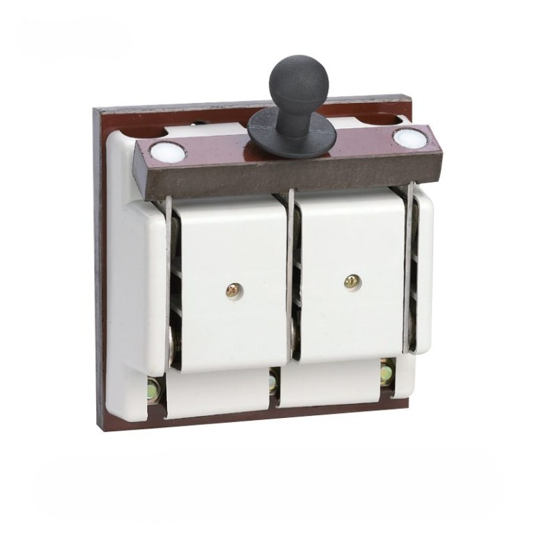
Rewirable or Kit Kat Fuse Unit is the most commonly used fuse in our day to day life. This fuse has mainly two parts. The unit in which the incoming and outgoing line or phase wire connected permanently is known as the fuse base. The removable part which holds the fuse wire and fits into the base is known as the fuse carrier. The fuse carrier is also known as a cutout.
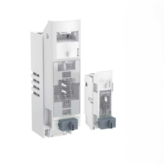
In cartridge fuse the fuse wire is enclosed in a transparent glass tube or bulb, the whole unit is sealed off. In case the fuse blows, it is to be replaced by a new one as the cartridge fuse can not be rewired due to its sealing.
For the small value of current interruption lead-tin, alloy fuse wire has been used in past. The most preferred lead-tin alloy for fuse wire containing 37% lead and 63% tin. This alloy fuse wire is also known as Eutectic Alloy Fuse Wire. This type of alloy has some specific characteristics due to which this is preferred as fuse wire.
It has a high brinner hardness and has less tendency to spread over.
The alloy metal is quite homogeneous.
If the fusing characteristics of eutectic alloy and other composition of alloys is studied there is only one arrest point in the eutectic alloy as compared to two other types of alloys.
Approximate fusing currents of lead-tin alloy fuse wire in the air
Diameter of wire in inch |
Fusing Current in A |
Maximum safe Current in A |
0.02 |
3 |
2 |
0.022 |
3.5 |
2.3 |
0.024 |
4 |
2.6 |
0.028 |
5 |
3.3 |
0.032 |
6 |
4.1 |
0.036 |
7 |
4.8 |
0.048 |
10 |
7 |
0.064 |
16 |
11 |
NB: – The minimum length of the fuse wire used must be 2.5 to 3.5 inches. The values in the above table are true only when the fuse wire does not touch the fuse grip body because when the fuse wire comes in contact with porcelain or other the value of fusing current increases as the heat dissipation rate from the current-carrying fuse wire, is increased. Hence precaution should always be taken during rewiring a fuse wire on a fuse grip so that it should not touch the fuse grip body.


HRC fuse or high rupturing capacity fuse– In that type of fuse, the fuse wire or element can carry short circuit heavy current for a known time period. During this time if the fault gets removed, then it does not blow off. Otherwise, it blows off or melts. The enclosure of HRC fuse is either of glass or some other chemical compound.
This enclosure is sufficiently airtight to avoid the effect of the atmosphere on the fuse materials. The ceramic enclosure having a metal end cap at both heads, to which fusible silver wire gets welded. There is a space within the enclosure, surrounding the fuse wire or fuse element, completely packed with a filling powder.
This type of fuse is reliable and has inverse time characteristic, which means if the fault current is high then rupture time is less, and if the fault current is not so high, then rupture-time is long.
When the overrated current flows through the fuse element of the high rupturing capacity fuse the element is melted and vaporized.
The filling powder is of such a quantity that the chemical reaction between the silver vapor and the filling powder forms a high electrical resistance substance which very much helps in quenching the arc.
Statement: Respect the original, good articles worth sharing, if there is infringement please contact delete.