Working Principle and Maintenance Key Points of 10kV High-Voltage Reactive Power Compensation Device

The 10kV high-voltage reactive power compensation device is an essential and indispensable component in modern power systems. By providing or absorbing reactive power, it effectively addresses issues such as low power factor, high line losses, and voltage fluctuations caused by reactive power demand, playing a key role in improving the economy, safety, and power quality of grid operation. High-voltage 10kV reactive power compensation is a critical device for ensuring safe and economical grid operation.
Understanding its working principle is the basis for maintenance, while strictly implementing a regular maintenance plan centered on preventive testing and condition monitoring—and always prioritizing safety—is the fundamental guarantee for ensuring long-term reliable operation. Maintenance work must be carried out by qualified and experienced personnel in accordance with established procedures. The following is a detailed explanation of the working principle and maintenance essentials of 10kV high-voltage reactive power compensation systems.
1. Working Principle of 10kV High-Voltage Reactive Power Compensation
Core Objective: Improve grid power factor, reduce line losses, stabilize system voltage, and enhance power supply quality.
1.1 Compensation Principle
Source of Reactive Power: Inductive loads in the power grid (e.g., motors, transformers) require the establishment of a magnetic field during operation, consuming lagging reactive power (Q).
Compensation Method: Capacitor banks are connected in parallel, generating leading capacitive reactive power (Qc) to offset the inductive reactive power (Ql).
Result: The total reactive power (Q) required by the system is reduced, the power factor (Cosφ = P / S) is improved, and the apparent power (S) is lowered.
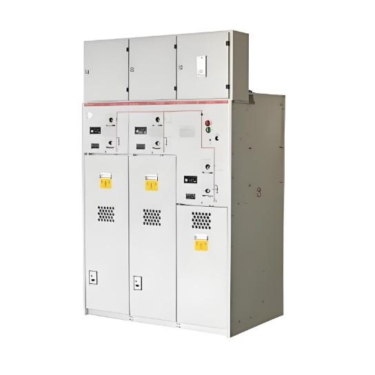
1.2 Components of the Compensation Device
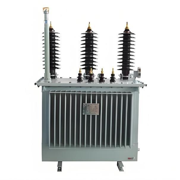
High-Voltage Shunt Capacitor Bank: The core component that provides capacitive reactive power. Typically consists of multiple capacitor units connected in series and parallel to meet 10kV voltage and required capacity requirements.
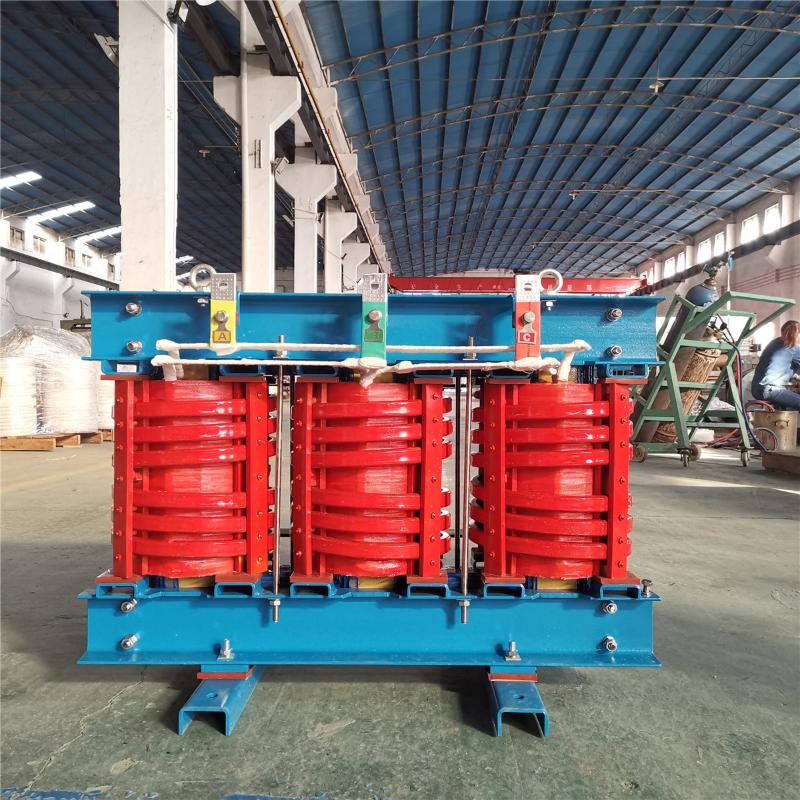
Series Reactor:
Current-Limiting Reactor: Limits inrush current at the moment of capacitor switching (typically 5–20 times the rated current), protecting the capacitors and switching equipment.
Filter Reactor: Forms an LC tuned circuit with the capacitor (usually tuned below the 5th, 7th, or a specific harmonic frequency), suppressing harmonic currents from entering the capacitor, preventing harmonic amplification and resonance, thus protecting the capacitor.
High-Voltage Switching Equipment:
Vacuum Contactor or Vacuum Circuit Breaker: Used to switch capacitor banks in or out. Vacuum contactors are more commonly used and suitable for frequent operations.
Isolating Switch / Grounding Switch: Used during maintenance to isolate the power source and ensure reliable grounding for safety.
Discharge Device:
Discharge Coil or Discharge Resistor: After the capacitor bank is disconnected, it quickly discharges the stored charge on the capacitor terminals (typically required to reduce residual voltage to below 50V within 5 seconds), ensuring safety during maintenance. Discharge coils are more commonly used.
Protection Devices:
Fuse: Protects individual capacitors against internal faults (expulsion-type fuse).
Relay Protection: Includes overcurrent protection (phase-to-phase short circuit), unbalance protection (internal capacitor element breakdown or fuse blowout), overvoltage protection, undervoltage protection, harmonic overlimit protection, open-delta voltage protection, etc.
Measurement and Control Devices:
Controller: Continuously monitors system voltage, current, power factor, harmonic current, harmonic voltage distortion rate, and other parameters. Automatically controls the switching of capacitor banks according to preset strategies (e.g., target power factor, target voltage, harmonic over-limit protection, time-based programs).
Current Transformer (CT), Voltage Transformer (PT): Provide signals for measurement and protection.

1.3 Operational Process
Monitoring: The controller continuously monitors parameters such as power factor, voltage, and reactive power demand of the grid.
Decision: When the power factor drops below a set lower limit (e.g., 0.9 lagging), or when the system needs additional reactive power, the controller issues an energizing command.
Energizing: The control circuit drives the vacuum contactor to close, connecting the capacitor bank (usually through a series reactor) in parallel to the 10kV busbar.
Compensation: The capacitor bank supplies capacitive reactive power to the system, offsetting part of the inductive reactive power, improving the power factor, and supporting the voltage.
De-energizing: When the power factor exceeds a set upper limit (e.g., 0.98 leading, which may cause overcompensation), or when system voltage is too high, or when load reduction leads to decreased reactive power demand, the controller issues a de-energizing command, the vacuum contactor opens, and the capacitor bank is taken out of service.
Discharge: After the capacitor bank is disconnected, the discharge device (discharge coil) automatically operates, quickly discharging the stored energy.
2. Maintenance of 10kV High-Voltage Reactive Power Compensation Devices
Core Objective: Ensure safe, reliable, and efficient operation, and extend equipment service life.
2.1 Daily Inspection
Visual Inspection: Check capacitor casing for bulging, oil leakage, rust, or paint peeling; check bushings for cracks, contamination, or flashover traces; check connection points for looseness, overheating (infrared thermography), or discoloration.
Operating Sound: Listen for abnormal vibration or noise from reactors, discharge coils, or capacitors (e.g., an abnormally increased "humming" sound may indicate internal looseness).
Instrument Indication: Check if the indications of voltmeters, ammeters, power factor meters, and reactive power meters are normal, and compare with the controller display values.
Environmental Check: Check indoor ventilation, ambient temperature, and humidity to ensure they are within allowable limits; check for dust accumulation or signs of small animal intrusion; check if fences and labels are intact.
Protection Signals: Check if there are any alarm or trip signals from the protection devices.
2.2 Periodic Maintenance (Typically Every Six Months to One Year)
Power-Down Cleaning: Thoroughly remove dust and dirt from the surfaces of capacitor casings, bushings, insulators, busbars, frames, reactors, and switchgear (using dry, lint-free cloths or special tools, avoiding insulation damage). (Important! Cleaning of high-voltage equipment must be done after power-off, voltage testing, and grounding!)
Tightening Connections: Check and tighten all electrical connection bolts (busbar connections, capacitor terminal connections, grounding wires, etc.) to ensure good contact and prevent overheating. Operate according to specified torque.
Capacitor Testing:
Capacitance Measurement: Use a dedicated capacitance bridge to measure the total capacitance of each phase or each branch (if applicable), and compare with nameplate values or historical data. If deviation exceeds ±5% or shows significant change (especially decrease), it requires close attention, possibly indicating internal component damage. The capacitance value of a single capacitor should not deviate from the rated value by more than -5% to +10%.
Insulation Resistance Test: Measure the insulation resistance between poles and between pole and case (using a 2500V megohmmeter), which should meet regulatory requirements (typically, inter-pole insulation resistance should be very high, pole-to-case insulation resistance > 1000MΩ). Must be fully discharged before and after testing!
Dissipation Factor (tanδ) Measurement: Can be performed if conditions allow, which is more sensitive in reflecting internal capacitor insulation moisture or deterioration. Should not show significant increase compared to factory or previous measurement values.
Reactor Inspection:
Check coil appearance for overheating, discoloration, insulation aging, or damage.
Check if core (if present) fasteners are loose.
Measure winding DC resistance, which should not show significant difference compared to factory or previous values (considering temperature influence).
Measure insulation resistance.
Discharge Device Check:
Check discharge coil appearance and wiring.
Verify discharge performance (under safety regulation permission, simulate operation to verify residual voltage drop speed).
Switching Equipment Maintenance:
Check vacuum interrupter appearance.
Check if operating mechanism operates flexibly and reliably; apply appropriate lubricant to lubrication points.
Measure main circuit contact resistance.
Perform mechanical characteristic tests (opening/closing time, synchronism, bounce, stroke, etc.).
Protection Device Calibration: Calibrate settings and perform transmission tests for overcurrent, unbalance, overvoltage, undervoltage, etc., according to regulations to ensure accurate and reliable operation. Check fuse appearance and indicator status.
Controller Check: Check if display, buttons, and communication are normal; verify sampling accuracy (compare voltage, current, power factor, etc., with standard meter); check if switching logic is correct.

2.3 Special Maintenance
Harmonic Environment: If the system has serious harmonics, strengthen monitoring of temperature rise of capacitors and reactors (infrared thermography), conduct regular harmonic tests, ensure tuning point settings are reasonable to avoid resonance. Add filtering devices if necessary.
Frequent Switching: Strengthen inspection of contact wear of vacuum contactors/circuit breakers, shorten their maintenance cycle.
After Faults: After protection operation (especially fuse blowout or unbalance protection operation), the cause must be thoroughly identified, damaged components replaced, and comprehensive inspection and testing completed before re-energization.
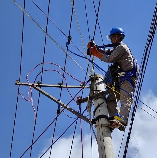
2.4 Safety Precautions (Most Important!)
Strictly enforce the "Two Tickets and Three Systems": Work Ticket, Operation Ticket; Shift Handover System, Patrol Inspection System, Equipment Periodic Testing and Rotation System.
Power-Off, Voltage Test, Grounding: Before any maintenance work, the power source must be reliably disconnected (including possible back-feeding from PT secondary side), use a qualified voltage tester to confirm absence of voltage, and install grounding wires at both ends of the work location. The capacitor bank must be fully discharged using a dedicated grounding rod and grounded before contact!
Dedicated Supervisor: Operation and maintenance of high-voltage equipment must have a dedicated supervisor.
Use Qualified Tools and Protection: Use tools with qualified insulation rating, wear insulating gloves, insulating boots, and other safety protective equipment.
Residual Voltage Awareness: Even after discharge, use a grounding rod to short-circuit capacitor terminals again before contact.
2.5 Record Keeping and Analysis
Record data from each inspection, maintenance, and test in detail (capacitance value, insulation resistance, temperature, protection action information, etc.).
Establish equipment files, perform trend analysis, and promptly identify potential defects.
Record abnormal conditions and handling processes.
3. Reference for Key Maintenance Intervals
Daily Inspection: Daily or weekly (depending on importance and operating environment).
Periodic Cleaning and Inspection (without power-off): Monthly or quarterly.
Periodic Maintenance (with power-off): Once to twice a year (combined with preventive testing).
Capacitor Capacitance/Insulation Resistance Measurement: Conducted during power-off maintenance; once within one year of commissioning, then once every 1–2 years.
Protection Device Calibration: Once a year.
Switching Equipment Characteristic Test: Combined with power-off maintenance, once every 1–2 years or when operation count reaches a certain value.
4. Notes
Ambient Temperature: The operating ambient temperature of capacitors must not exceed the specified upper limit (typically -40°C ~ +45°C), avoid direct sunlight.
Overvoltage: Capacitors can operate long-term at 1.1 times the rated voltage; avoid prolonged overvoltage operation.
Overcurrent: Capacitors can operate long-term at 1.3 times the rated current (considering harmonic and overvoltage effects).
Harmonics: Harmonics are one of the main causes of capacitor damage. The system harmonic background must be considered during design, and the reactor ratio configured reasonably. Strengthen harmonic monitoring during operation.