Cogeneration | Combined Heat and Power

03/19/2024

WechatIMG1749.jpeg

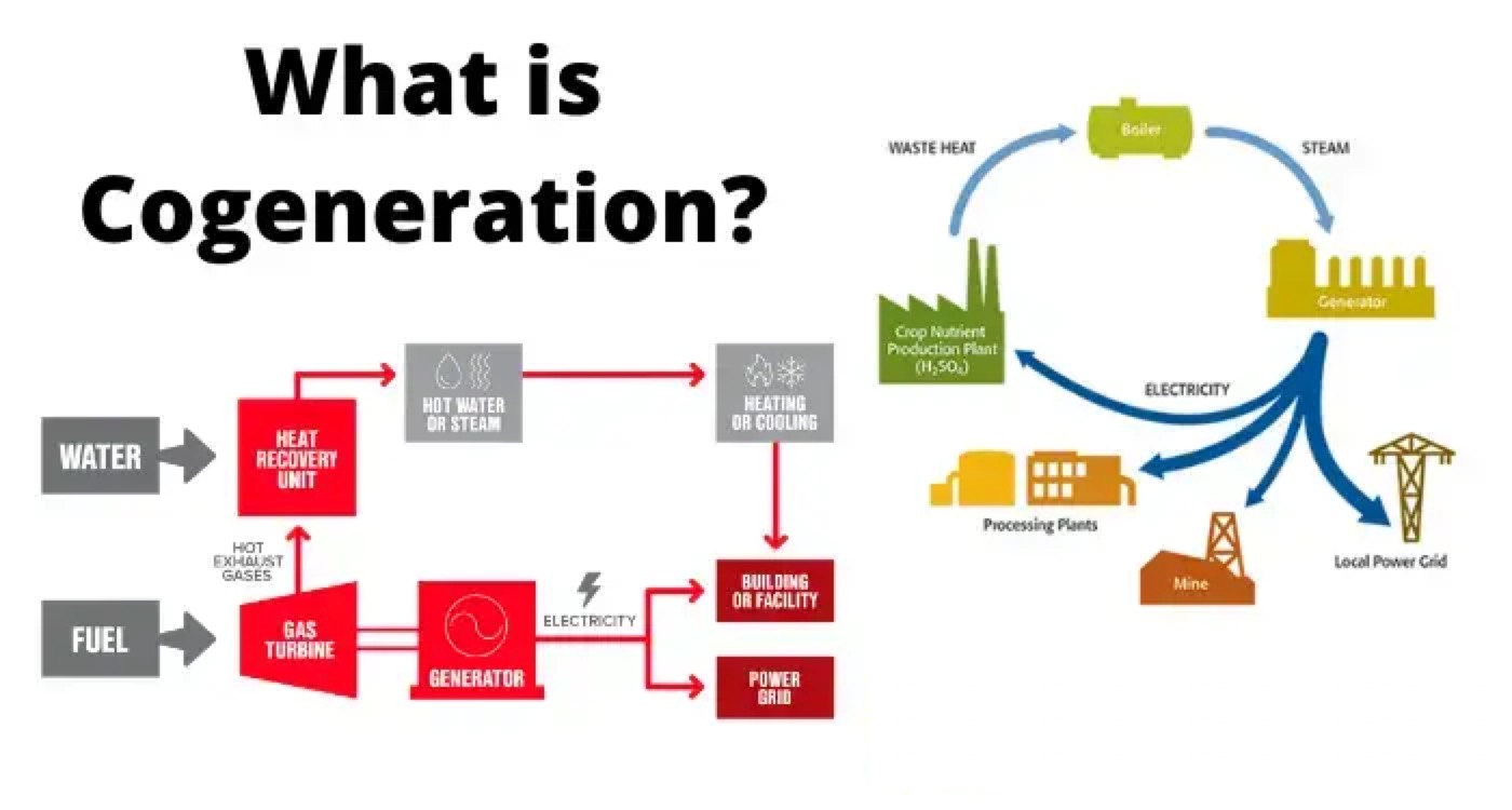
Cogeneration is also called as combined heat and power or combine heat and power. As it name indicates cogeneration works on concept of producing two different form of energy by using one single source of fuel. Out of these two forms one must be heat or thermal energy and other one is either electrical or mechanical energy.

Cogeneration is the most optimum, reliable, clean and efficient way of utilizing fuel. The fuel used may be natural gas, oil, diesel, propane, wood, bassage, coal etc. It works on very simple principle i.e the fuel is used to generate electricity and this electricity produces heat and this heat is used to boil water to produce steam, for space heating and even in cooling buildings.

In a conventional power plant, the fuel is burnt in a boiler, which in turn produces high pressure steam. This high pressure steam is used to drive a tribune, which is in turn is connected to an alternator and hence drive an alternator to produce electric energy.

The exhaust steam is then sent to the condenser, where it gets cool down and gets converted to water and hence return back to boiler for producing more electrical energy. The efficiency of this conventional power plant is 35 % only. In cogeneration plant the low pressure steam coming from turbine is not condense to form water, instead of it its used for heating or cooling in building and factories, as this low pressure steam from turbine has high thermal energy.

The cogeneration plant has high efficiency of around 80 – 90%. In India, the potential of power generation from cogeneration plant is more than 20,000 MW. The first commercial cogeneration plant was built and designed by Thomas Edison in New York in year 1882.
WechatIMG1750.png

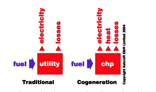
As shown in above diagram, in traditional power plant, when we gave fuel as input we get electrical energy and losses as output but in case of cogeneration with fuel as input, the output is electrical energy, heat or thermal energy and losses.

WechatIMG1751.png

In convential power plant, with 100 % energy input ,only 45 % of energy is used and rest 55 % is wasted but with cogeneration, the total energy used is 80% and energy wasted is only 20%. It means with cogeneration the fuel utiliuzation is more efficient and optimized and hence more economical.

Need for Cogeneration

  • Cogeneration helps to improve the efficiency of the plant.

  • Cogeneration reduce air emissions of particulate matter, nitrous oxides, sulphur dioxide, mercury and carbon dioxide which would otherwise leads to greenhouse effect.

  • It reduces cost of production and improve productivity.

  • Cogeneration system helps to save water consumption and water costs.

  • Cogeneration system is more economical as compared to conventional power plant.

Types of Cogeneration Power Plants

In a typical Combined heat and power plant system there is a steam or gas turbine which take steam and drives an alternator. A waste heat exchanger is also installed in cogeneration plant, which recovers the excess heat or exhaust gas from the electric generator to in turn generate steam or hot water.
There are basically two types of cogeneration power plants, such as-

  • Topping cycle power plant

  • Bottoming cycle power plant

Topping Cycle Power Plant

In this type of Combine Heat and Power plant electricity is generated first and then waste or exhaust steam is used to heating water or building. There are basically four types of topping cycles.

  1. Combined-cycle topping CHP plant- In this type of plant the fuel is firstly burnt in a steam boiler. The steam so produced in a boiler is used to drive turbine and hence synchronous generator which in turn produces electrical energy. The exhaust from this turbine can be either used to provide usable heat, or can be send to a heat recovery system to generate steam, which maybe further used to drive a secondary steam turbine.

  2. Steam-turbine topping CHP Plant- In this the fuel is burned to produce steam, which generates power. The exhaust steam is then used as low-pressure process steam to heat water for various purposes.

  3. Water turbine topping CHP Plant- In this type of CHP plant a jacket of cooling water is run through a heat recovery system to generate steam or hot water for space heating.

  4. Gas turbine topping CHP plant- In This topping plant a natural gas fired turbine is used to drives a synchronous generator to produce electricity. The exhaust gas is sent to a heat recovery boiler where it is used to convert water into steam, or to make usable heat for heating purposes.

Bottoming Cycle Power Plant

As its name indicate bottoming cycle is exactly opposite of topping cycle. In this type of CHP plant the excess heat from a manufacturing process is used to generate steam, and this steam is used for generating electrical energy. In this type of cycle no extra fuel is required to produce electricity, as fuel is already burnt in production process.

Configuration of Cogeneration Plant

  • Gas turbine Combine heat power plants which uses the waste heat in the flue gas emerging out of gas turbines.

  • Steam turbine Combine heat power plants that use the heating system as the jet steam condenser for the steam turbine.

  • Molten-carbonate fuel cells have a hot exhaust, very suitable for heating.

  • Combined cycle power plants adapted for Combine Heat and Power.

Statement: Respect the original, good articles worth sharing, if there is infringement please contact delete.

Hello,I'm Wdwiin. A decade of hands-on experience in electrical engineering, specializing in high-voltage systems, smart grids, and renewable energy technologies. Passionate about technical exchange and knowledge sharing, committed to interpreting industry trends with professional insights to empower peers. Connection creates value—let’s explore the boundless possibilities of the electrical world together!

What is the difference between a dielectric and an insulator?
Dielectrics and insulators are distinguished primarily by their applications. One of the main differences is that a dielectric can store electrical energy by becoming polarized in an electric field, whereas an insulator resists the flow of electrons to prevent current conduction. Other key differences between them are outlined in the comparison chart below.Definition of DielectricA dielectric material is a type of insulator that contains few or no free electrons. When subjected to an electric fi
08/30/2025
What losses occur during operation of the transformer? How to reduce losses?
Transformers experience various types of losses during operation, primarily categorized into two main types: copper losses and iron losses.Copper LossesCopper losses, also known as I²R losses, are caused by the electrical resistance of the transformer windings—typically made of copper. As current flows through the windings, energy is dissipated in the form of heat. These losses are proportional to the square of the load current (I²R), meaning they increase significantly with high
Rockwell
08/29/2025
Cable Fault Detection, Testing, Location and Repair
I. Methods for Cable Testing and Inspection:Insulation Resistance Test: Use an insulation resistance tester to measure the insulation resistance value of the cable. A high insulation resistance value indicates good insulation, while a low value may suggest insulation problems requiring further investigation.Voltage Withstand Test: Apply a high-voltage test using a high-voltage tester to verify whether the cable can withstand high voltage under its rated operating conditions. Under normal circums
08/29/2025
Cable Quality Inspection and Cable Detection & Testing
Power cable quality inspection and cable testing are conducted to ensure that the cable's quality and performance meet specified requirements, thereby guaranteeing the safe and stable operation of power systems. Below are some common contents of power cable quality inspection and cable testing:Visual Inspection: Check the cable surface for physical defects such as damage, deformation, or scratches to ensure the cable's exterior is intact.Dimensional Measurement: Measure dimensional parameters su
08/29/2025
Inquiry
Download
IEE-Business is dedicated to serving the personnel in the global power industry.
Join IEE-Business, not only can you discover power equipment and power knowledge, but also canhnd like - minded friends!