
Ang metodo sa pagkontrol sa bilis ni Ward Leonard nagoperasyon pinaagi sa pag-ajust sa voltaje nga gipasabot sa armature sa motor. Kini nga maong pamatasan nailhan sa unang higayon sa 1891, nagsilbing kaugalingong pagkakataas sa larangan sa pagkontrol sa elektrikong motor. Ang figure sa ubos nagpakita sa diagrama sa koneksyon alang sa pag-implementar sa metodo ni Ward Leonard aron mapahimulos ang bilis sa DC shunt motor, naghatag og malinaw nga visual representation sa sistema nga konpigurasyon ug operasyon.
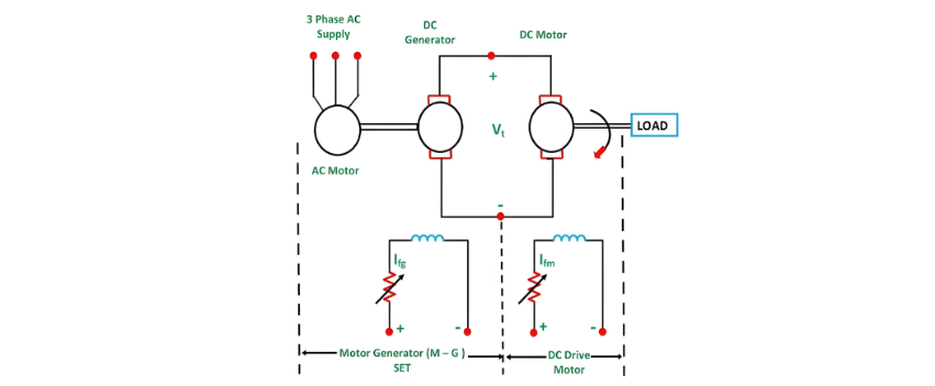
Sa sistema nga gi-describe sa itaas, M mao ang pangunang DC motor nga ang rotational speed mao ang target sa kontrol, samtang G mao ang separately excited DC generator. Ang generator G gipasabot pinaagi sa three-phase driving motor, mahimo kini usa ka induction motor o synchronous motor. Ang pairing sa AC driving motor ug DC generator kasagaran gitawag og Motor-Generator (M-G) set.
Ang voltage output sa generator mahimo mosulay pinaagi sa pagbag-o sa field current sa generator. Kapag nausab ang adjusted voltage gipasabot diretso sa armature sa pangunang DC motor, kini magresulta og corresponding change sa bilis sa motor M. Aron masiguro ang consistent performance sa panahon sa pagkontrol sa bilis, ang field current Ifm sa motor gipapanatili sa constant level, sumala usab sa stable nga field flux ϕm sa motor. Sa wala pa mopagbutok sa bilis sa motor, ang motor armature current Ia giregulate aron matugyan sa iyang rated value. Pinaagi sa pagbago sa generated field current Ifg, ang armature voltage Vt mahimo mogamit gikan sa zero hangtod sa iyang rated value.
Kini nga adjustment sa voltage nagresulta sa pagbago sa bilis sa motor gikan sa zero hangtod sa base speed. Tungod kay ang proseso sa pagkontrol sa bilis gipagbutok sa rated current Ia ug constant motor field flux ϕm, makamit ang constant torque, tungod kay ang torque directly proportional sa product sa armature current ug field flux hangtod sa rated speed. Tungod kay ang product sa torque ug bilis define power, ug ang torque constant sa scenario niini, ang power directly proportional sa bilis. Konsequensya, isip ang power output mogamay, ang bilis sa motor magamay usab.
Ang torque ug power characteristics sa kini nga sistema sa pagkontrol sa bilis nagpakita sa figure sa ubos, naghatag og visual representation sa paano kini mga parameter interact ug bag-o sa panahon sa operasyon.
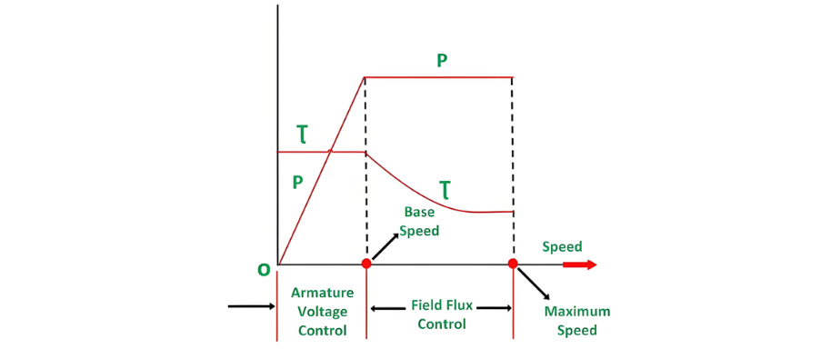
Sa summary, ang armature voltage control method makapahimulos og constant torque ug variable power drive para sa bilis dihang duol sa base speed. Sa laing bahin, ang field flux control method mogamit kung ang bilis mogamay sa base speed. Sa kini nga operational mode, ang armature current consistently maintained sa iyang rated value, ug ang generator voltage Vt remain constant.
Kon ang motor field current mobaba, ang motor field flux usab mobaba, effectively weakening the field to achieve higher speeds. Tungod kay ang Vt Ia ug E Ia remain constant, ang electromagnetic torque directly proportional sa product sa field flux ϕm ug armature current Ia. Konsequensya, ang reduction sa motor's field flux lead sa decrease sa torque.
Isip resulta, ang torque mobaba kon ang bilis mogamay. Busa, sa field control mode, para sa bilis dihang gamay sa base speed, makamit ang constant power ug variable torque operation. Kon ang wide-range speed control importante, ang combination sa armature voltage control ug field flux control gigamit. Kini nga combined approach allows the ratio of the maximum to minimum available speeds to range from 20 to 40. Sa closed-loop control systems, this speed range can be extended up to 200.
Ang driving motor mahimo usa ka induction motor o synchronous motor. Ang induction motor typically operates at a lagging power factor. Sa laing bahin, ang synchronous motor can be operated at a leading power factor through over-excitation of its field. An over-excited synchronous motor generates leading reactive power, which effectively compensates for the lagging reactive power consumed by other inductive loads, thereby improving the overall power factor.
Kon magdeal sa heavy ug intermittent loads, ang slip ring induction motor often utilized as the prime mover, ug ang flywheel mounted on its shaft. Kini nga configuration, known as the Ward Leonard - Ilgener scheme, helps to prevent significant fluctuations in the supply current. However, when a synchronous motor serves as the driving motor, mounting a flywheel on its shaft cannot reduce fluctuations, since a synchronous motor always runs at a constant speed.
Advantages of Ward Leonard Drives
The Ward Leonard drive offers several key advantages:
It allows for smooth speed control of a DC motor over a broad range in both directions.
It has an inherent braking capability. By using an over-excited synchronous motor as the drive, the lagging reactive volt-amperes are compensated, enhancing the overall power factor.
In applications with intermittent loads, such as rolling mills, an induction motor with a flywheel can be employed to smooth out the intermittent loading, reducing its impact on the system.
Drawbacks of Classical Ward Leonard System
The classical Ward Leonard system, which relies on rotating Motor-Generator sets, has the following limitations:
The initial investment for the system is substantial due to the requirement of installing a motor-generator set with the same rating as the main DC motor.
It has a large physical size and significant weight.
It demands a large floor area for installation. The foundation required for the system is costly.
Frequent maintenance is needed.
It incurs higher losses during operation.
Its overall efficiency is relatively low.
The drive generates a significant amount of noise.
Applications of Ward Leonard Drives
Ward Leonard drives are ideal for scenarios where smooth, bidirectional, and wide-range speed control of DC motors is essential. Some common applications include:
Rolling mills
Elevators
Cranes
Paper mills
Diesel-electric locomotives
Mine hoists
Solid State Control or Static Ward Leonard System
In modern applications, the Static Ward Leonard system is widely preferred. In this system, the traditional rotating motor-generator (M-G) set is replaced by a solid-state converter for controlling the speed of the DC motor. Controlled rectifiers and choppers are commonly used as converters.
When the power source is an AC supply, controlled rectifiers are utilized to transform the fixed AC supply voltage into a variable DC supply voltage. In the case of a DC supply, choppers are employed to obtain a variable DC voltage from the fixed DC source.
In an alternative form of the Ward Leonard drive, non-electrical prime movers can also be used to drive the DC generator. For instance, in DC electric locomotives, the DC generator is powered by a diesel engine or a gas turbine, and this setup is also applicable in ship propulsion drives. In such systems, regenerative braking is not feasible because energy cannot flow in the reverse direction through the prime mover.


