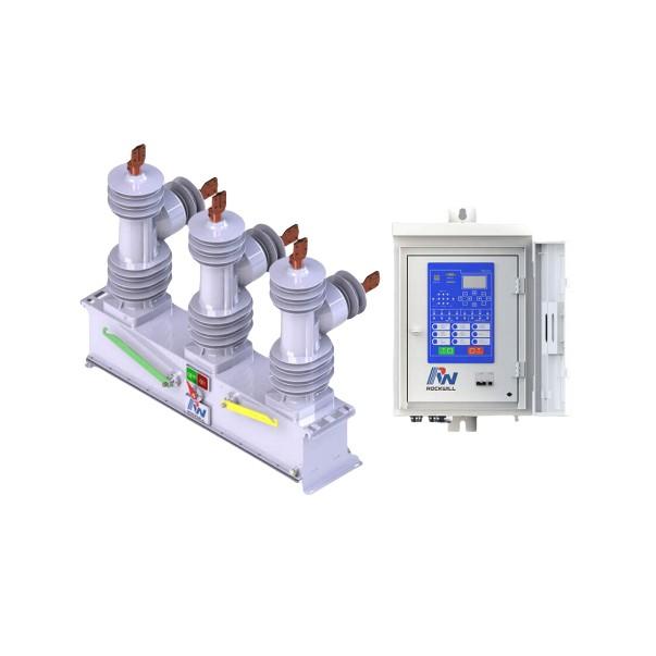
Distribution Lines: A Key Component of Power Systems
Distribution lines are a major component of power systems. On the same voltage-level busbar, multiple distribution lines (for input or output) are connected, each with numerous branches arranged radially and linked to distribution transformers. After being stepped down to low voltage by these transformers, electricity is supplied to a wide range of end users. In such distribution networks, faults such as phase-to-phase short circuits, overcurrent (overload), and single-phase-to-ground faults frequently occur. Among these, single-phase-to-ground faults are the most common, accounting for over 70% of total system faults. Moreover, many short-circuit faults evolve from single-phase-to-ground faults that escalate into multi-phase ground faults.
Single-phase-to-ground faults refer to situations where any one of the three phases (A, B, or C) on a distribution line breaks and falls to the ground, contacts trees, buildings, poles, or towers, forming a conductive path with earth. They can also result from overvoltage caused by lightning or other atmospheric conditions, which damages the insulation of distribution equipment, causing a significant drop in insulation resistance to ground.
When a single-phase-to-ground fault occurs in a low-current grounding system, a complete fault loop is not directly formed. The capacitive grounding current is much smaller than the load current, and the system's line voltages remain symmetrical, so power supply to users is not immediately disrupted. Therefore, regulations permit continued operation with one ground fault for up to 2 hours. However, the voltage on the non-faulted phases rises relative to ground, posing a threat to insulation. Hence, lines with an existing ground fault must be quickly identified and addressed.
I. Identification of Single-Phase-to-Ground Faults on 35kV Auxiliary Busbars
When single-phase-to-ground faults, ferroresonance, phase loss, or high-voltage fuse blowouts in voltage transformers (VTs) occur, the observed phenomena can be similar, but careful analysis reveals distinct differences.
Single-Phase-to-Ground Fault:
The substation and SCADA system will issue signals such as “35kV busbar grounding” or “Arc Suppression Coil No. X activated.” Relay protection does not trip but triggers alarm signals. The voltage of the faulted phase drops, while the other two phase voltages rise. The VT indicator light for the faulted phase dims, while the other two brighten. In a solid (metallic) ground fault, the faulted phase voltage drops to zero, and the other two phase-to-ground voltages increase by √3 times, while line voltages remain unchanged. The VT’s 3V₀ output reads around 100V, and the harmonic suppression light illuminates. The arc suppression coil carries current, equal to the compensation current corresponding to its tap setting. If a small-current fault line selector is installed, it will activate and identify the faulted line. If the fault is within the substation, physical signs such as visible arcing, smoke, and loud electrical noises make the fault point easier to identify.
Ferroresonance:
A neutral point displacement voltage is generated, altering the three-phase phase voltages. Typically, one phase voltage increases while the other two decrease, or vice versa, and line voltages also change accordingly. Since the neutral voltage is non-zero, current flows through the arc suppression coil, and “busbar grounding” signals may appear depending on the magnitude of the displacement voltage.
Phase Loss:
The voltage on the upstream side of the lost phase rises to 1.5 times the normal voltage, while downstream voltage drops to zero. The current in the faulted phase becomes zero, and the other two phase voltages slightly decrease. Line voltages remain unchanged. 3V₀ reads around 50V, the arc suppression coil carries current, and a grounding signal is issued. Users are likely to report power outages.
VT High-Voltage Fuse Blowout:
The voltage of the blown phase drops significantly (typically below half the normal phase voltage), while other phase voltages do not rise. Line voltages become unbalanced. All outgoing circuits on the busbar trigger a “voltage circuit open” alarm. 3V₀ reads approximately 33V, and a grounding signal is issued.
Although these four conditions—single-phase-to-ground, ferroresonance, phase loss, and VT fuse blowout—exhibit similar symptoms, a thorough analysis of phase voltage, line voltage, 3V₀, arc suppression coil current, SCADA automation signals, and reports from control room operators can accurately distinguish a single-phase-to-ground fault.
II. Handling Process for 35kV Auxiliary Bus Single-Phase-to-Ground Faults
When a 35kV line grounding fault occurs, the Wan’an substation’s 35kV busbar issues a grounding alarm. Personnel at the central control station should be notified immediately to inspect in-station equipment and protection status (including 3V₀ voltage, small-current fault line selector status, arc suppression coil temperature/current, etc.), and the line operation team should be dispatched for line patrol. After receiving feedback from the central station confirming a ground fault, trial switching (trial tripping) of lines should be performed. Before trial switching, critical users must be notified.
For systems without trial switching devices, remote tripping via SCADA is possible, but loads at downstream substations must first be transferred. In systems with internal bridge connections, automatic transfer switches (ATS) must be disabled to prevent them from transferring the fault to healthy sections.Once a specific line is identified as faulted, priority should be given to transferring its load before taking the faulty line out of service. The line operation team and central station personnel should then be notified to patrol the 35kV line and inspect the 35kV equipment within the associated 35kV substation.
To prevent the fault from escalating into a phase-to-phase short circuit—which could cause sudden outages—faulty equipment must be quickly located and isolated. Additionally, to prevent overheating and damage to the arc suppression coil, the faulted equipment should generally be isolated within 2 hours. The coil’s temperature rise should be monitored and kept below 55°C. If exceeded, single-phase-to-ground operation must be stopped immediately, and the faulted equipment disconnected. If the grounding condition persists beyond 2 hours, the situation must be reported to senior management.
III. Conclusion
When a single-phase-to-ground fault occurs on a distribution line, the line voltage magnitude and phase remain unchanged, allowing short-term continued operation without disconnecting the faulty equipment. While this improves supply reliability, the voltage on the two healthy phases rises to line-to-line levels, increasing the risk of insulation breakdown and subsequent two-phase-to-ground short circuits. This poses significant risks to the safe and economical operation of substation equipment and the distribution network. Therefore, such faults should be prevented where possible, and once they occur, the fault point must be quickly located and eliminated to enhance overall power supply reliability.