• Product
  • Suppliers
  • Manufacturers
  • Solutions
  • Free tools
  • Knowledges
  • Experts
  • Communities
Search


Transformer: What is it?

Electrical4u
Electrical4u
Field: Basic Electrical
0
China

image.png

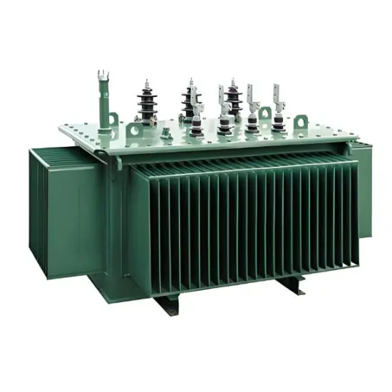
What is a Transformer?

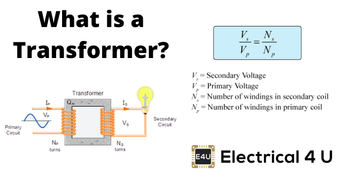
transformer is defined as a passive electrical device that transfers electrical energy from one circuit to another through the process of electromagnetic induction. It is most commonly used to increase (‘step up’) or decrease (‘step down’) voltage levels between circuits.

Working Principle of Transformer

The working principle of a transformer is very simple. Mutual induction between two or more windings (also known as coils) allows for electrical energy to be transferred between circuits. This principle is explained in further detail below.

Transformer Theory

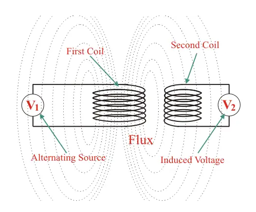
Say you have one winding (also known as a coil) which is supplied by an alternating electrical source. The alternating current through the winding produces a continually changing and alternating flux that surrounds the winding.

If another winding is brought close to this winding, some portion of this alternating flux will link with the second winding. As this flux is continually changing in its amplitude and direction, there must be a changing flux linkage in the second winding or coil.

According to Faraday’s law of electromagnetic induction, there will be an EMF induced in the second winding. If the circuit of this secondary winding is closed, then a current will flow through it. This is the basic working principle of a transformer.

Let us use electrical symbols to help visualize this. The winding which receives electrical power from the source is known as the ‘primary winding’. In the diagram below this is the ‘First Coil’.

image.png

The winding which gives the desired output voltage due to mutual induction is commonly known as the ‘secondary winding’. This is the ‘Second Coil’ in the diagram above.

A transformer that increases voltage between the primary to secondary windings is defined as a step-up transformer. Conversely, a transformer that decreases voltage between the primary to secondary windings is defined as a step-down transformer.

Whether the transformer increases or decreases the voltage level depends on the relative number of turns between the primary and secondary side of the transformer.

If there are more turns on the primary coil than the secondary coil than the voltage will decrease (step down).

If there are less turns on the primary coil than the secondary coil than the voltage will increase (step up).

While the diagram of the transformer above is theoretically possible in an ideal transformer – it is not very practical. This is because in the open air only a very tiny portion of the flux produced from the first coil will link with the second coil. So the current that flows through the closed circuit connected to the secondary winding will be extremely small (and difficult to measure).

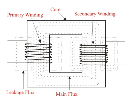
The rate of change of flux linkage depends upon the amount of linked flux with the second winding. So ideally almost all of the flux of primary winding should link to the secondary winding. This is effectively and efficiently done by using a core type transformer. This provides a low reluctance path common to both of the windings.

image.png

The purpose of the transformer core is to provide a low reluctance path, through which the maximum amount of flux produced by the primary winding is passed through and linked with the secondary winding.

The current that initially passes through the transformer when it is switched on is known as the transformer inrush current.

If you would prefer an animated explanation, below is a video explaining exactly how a transformer works:

Transformer Parts And Construction

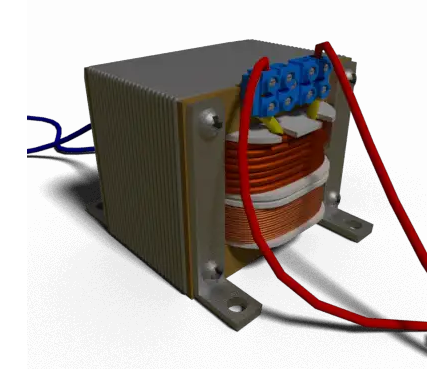
The three main parts of a transformer:

  • Primary Winding of Transformer

  • Magnetic Core of Transformer

  • Secondary Winding of Transformer

Primary Winding of Transformer

Which produces magnetic flux when it is connected to an electrical source.

Magnetic Core of Transformer

The magnetic flux produced by the primary winding, that will pass through this low reluctance path linked with secondary winding and create a closed magnetic circuit.

Secondary Winding of Transformer

The flux, produced by primary winding, passes through the core, will link with the secondary winding. This winding also wounds on the same core and gives the desired output of the transformer.

image.png

Statement: Respect the original, good articles worth sharing, if there is infringement please contact delete.

Give a tip and encourage the author!
Recommended
What causes a transformer to be noisier under no-load conditions?
When a transformer is operating under no-load conditions, it often produces louder noise than under full load. The primary reason is that, with no load on the secondary winding, the primary voltage tends to be slightly higher than nominal. For example, while the rated voltage is typically 10 kV, the actual no-load voltage may reach around 10.5 kV.This elevated voltage increases the magnetic flux density (B) in the core. According to the formula:B = 45 × Et / S(where Et is the designed volts-per-
Noah
11/05/2025
Under what circumstances should an arc suppression coil be taken out of service when it is installed?
When installing an arc suppression coil, it is important to identify the conditions under which the coil should be taken out of service. The arc suppression coil should be disconnected under the following circumstances: When a transformer is being de-energized, the neutral-point disconnector must be opened first before performing any switching operations on the transformer. The energizing sequence is the reverse: the neutral-point disconnector should be closed only after the transformer is energ
Echo
11/05/2025
What fire prevention measures are available for power transformer failures?
Failures in power transformers are commonly caused by severe overload operation, short circuits due to winding insulation degradation, aging of transformer oil, excessive contact resistance at connections or tap changers, failure of high- or low-voltage fuses to operate during external short circuits, core damage, internal arcing in oil, and lightning strikes.Since transformers are filled with insulating oil, fires can have severe consequences—ranging from oil spraying and ignition to, in extrem
Noah
11/05/2025
What are the common faults encountered during the operation of power transformer longitudinal differential protection?
Transformer Longitudinal Differential Protection: Common Issues and SolutionsTransformer longitudinal differential protection is the most complex among all component differential protections. Misoperations occasionally occur during operation. According to 1997 statistics from the North China Power Grid for transformers rated 220 kV and above, there were 18 incorrect operations in total, of which 5 were due to longitudinal differential protection—accounting for approximately one-third. Causes of
Felix Spark
11/05/2025
Related Products
Send inquiry
Download
Get the IEE Business Application
Use the IEE-Business app to find equipment, obtain solutions, connect with experts, and participate in industry collaboration anytime, anywhere—fully supporting the development of your power projects and business.