• Product
  • Suppliers
  • Manufacturers
  • Solutions
  • Free tools
  • Knowledges
  • Experts
  • Communities
Search


Polarity Test of a Transformer – Circuit Diagram and Working

Edwiin
Edwiin
Field: Power switch
China

Polarity in Two-Winding Transformers

In two-winding transformers, one terminal of a winding is always positive relative to the other at any instant. Transformer polarity refers to the relative direction of induced voltages between the high-voltage (HV) and low-voltage (LV) windings. In practical transformers, winding terminals are brought out as leads, and polarity defines how these leads are connected and labeled.

Significance of Transformer Polarity

Understanding polarity is critical for several operational and engineering tasks:

  • Instrument Transformer Connection (CTs and PTs):Proper polarity ensures accurate measurement of current and voltage in power systems.

  • Protective Relay Coordination:Correct polarity is essential for relays to detect faults and operate reliably.

  • Three-Phase Transformer Construction:Polarity determines how single-phase windings are interconnected to form three-phase configurations (e.g., delta or wye).

  • Parallel Operation of Transformers:Transformers in parallel must have identical polarity to avoid circulating currents and magnetic flux cancellation.

Terminal Markings and Polarity Identification

Instead of using traditional dot markings, it is often clearer to use H1/H2 for primary (HV) windings and X1/X2 for secondary (LV) windings to denote polarity:

  • H1 and H2: Markers for the primary winding terminals, indicating the start and end of the HV winding.

  • X1 and X2: Corresponding markers for the secondary winding terminals (LV side).

During polarity testing, these labels help identify:

  • The instantaneous voltage relationship between HV and LV windings (e.g., H1 and X1 are "in-phase" if polarity is additive).

  • Whether the transformer has additive (series-aiding) or subtractive (series-opposing) polarity, which impacts how windings are connected in circuits.

Key Consideration

Incorrect polarity can lead to:

  • Faulty measurements in instrument transformers.

  • Malfunctioning protective relays.

  • Excessive circulating currents or overheating in parallel-connected transformers.

By standardizing on clear terminal markings (H1/H2 and X1/X2), engineers and technicians can ensure proper transformer polarity, enhancing the safety, reliability, and efficiency of power systems.

Transformer Polarity
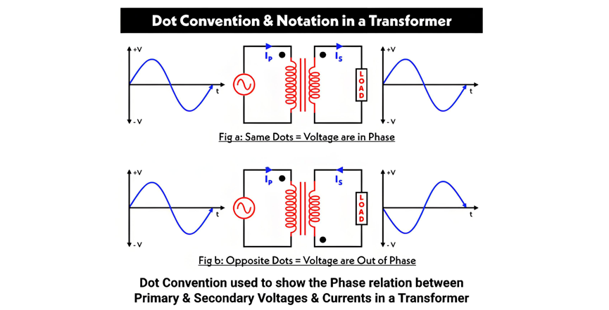
The dot convention (or dot notation) is a standard method used to denote the polarity of windings in a transformer.

Transformer Polarity and Dot Convention

In Figure A, two dots are placed on the same side of the primary and secondary windings. This indicates that the current entering the dotted terminal of the primary winding has the same direction as the current leaving the dotted terminal of the secondary winding. Consequently, the voltages at the dotted ends are in phase—if the voltage at the dotted point of the primary is positive, the voltage at the dotted point of the secondary will also be positive.


In Figure B, the dots are positioned on opposite sides of the windings, signifying that the windings are wound in opposite directions around the core. Here, the voltages at the dotted points are out of phase: a positive voltage at the primary’s dotted terminal corresponds to a negative voltage at the secondary’s dotted terminal.

Additive vs. Subtractive Polarity

Transformer polarity can be classified as additive or subtractive. To determine which type applies, connect one terminal of the primary winding to one terminal of the secondary winding and attach a voltmeter across the remaining terminals of both windings.
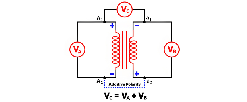
Additive Polarity

  • Voltmeter Reading: Measures the sum of the primary voltage VA and secondary voltage VB, denoted as VC.

  • Formula: VC = VA + VB.

  • Winding Configuration: The windings are oriented such that their magnetic fluxes oppose each other when currents flow into the dotted terminals.

The circuit diagram of additive polarity is shown in the figure below.

Subtractive Polarity

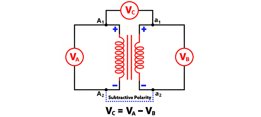
In subtractive polarity, the voltmeter measures the difference between the primary voltage and the secondary voltage. Denoted as VC, the voltmeter reading is expressed by the equation:

The circuit diagram of subtractive polarity is shown in the figure below.


Circuit Diagram of Polarity Test

The circuit diagram of the polarity test is shown in the figure below.

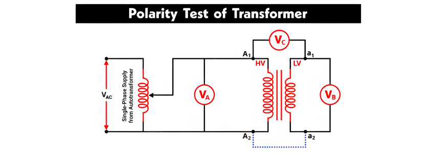
Polarity Testing of Transformers

The primary winding terminals are denoted as A1, A2, and the secondary winding terminals as a1, a2. As shown in the figure, a voltmeter VA is connected across the primary winding, VB across the secondary winding, and VC between the primary terminal A1 and secondary terminal a1.

An autotransformer is used to provide a variable AC supply to the primary winding. All voltmeter readings are recorded under this configuration:

  • If the voltmeter VC reads the sum of VA and VB, the transformer exhibits additive polarity.

  • If VC) reads the difference between VA and VB, the transformer exhibits subtractive polarity.

Polarity Test Using a DC Source (Battery)

The AC voltage method described above can be impractical for determining the relative polarity of two-winding transformers. A more convenient approach uses a DC source (battery), a switch, and a DC permanent-magnet voltmeter. The connection diagram for this method—including the correct battery polarity—is shown in the figure below.

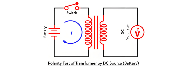
A switch is connected in series with the primary winding. When the switch is closed, the battery is connected to the primary winding, allowing current to flow through it. This generates flux linkage in both windings, inducing electromotive force (EMF) in both the primary and secondary windings.

The induced EMF in the primary winding has a positive polarity at the end connected to the battery's positive terminal. To determine the secondary winding's polarity:

  • If the DC voltmeter connected across the secondary winding shows a positive reading at the moment the switch is closed, the secondary terminal connected to the voltmeter's positive probe has the same polarity as the primary's positive terminal (i.e., the dotted terminals are correctly identified).

  • If the voltmeter deflects to the negative side, the secondary terminal connected to the voltmeter's positive probe has opposite polarity to the primary's positive terminal.

Give a tip and encourage the author!
Recommended
SST Technology: Full-Scenario Analysis in Power Generation, Transmission, Distribution, and Consumption
I. Research BackgroundPower System Transformation NeedsChanges in energy structure are placing higher demands on power systems. Traditional power systems are transitioning toward new-generation power systems, with the core differences between them outlined as follows: Dimension Traditional Power System New-Type Power System Technical Foundation Form Mechanical Electromagnetic System Dominated by Synchronous Machines and Power Electronic Equipment Generation-Side Form M
Echo
10/28/2025
Understanding Rectifier and Power Transformer Variations
Differences Between Rectifier Transformers and Power TransformersRectifier transformers and power transformers both belong to the transformer family, but they differ fundamentally in application and functional characteristics. The transformers commonly seen on utility poles are typically power transformers, while those supplying electrolytic cells or electroplating equipment in factories are usually rectifier transformers. Understanding their differences requires examining three aspects: working
Echo
10/27/2025
SST Transformer Core Loss Calculation and Winding Optimization Guide
SST High-Frequency Isolated Transformer Core Design and Calculation Material Characteristics Impact:Core material exhibits varying loss behavior under different temperatures, frequencies, and flux densities. These characteristics form the foundation of overall core loss and require precise understanding of nonlinear properties. Stray Magnetic Field Interference:High-frequency stray magnetic fields around windings can induce additional core losses. If not properly managed, these parasitic losses
Dyson
10/27/2025
Upgrade Traditional Transformers: Amorphous or Solid-State?
I. Core Innovation: A Dual Revolution in Materials and StructureTwo key innovations:Material Innovation: Amorphous AlloyWhat it is: A metallic material formed by ultra-rapid solidification, featuring a disordered, non-crystalline atomic structure.Key Advantage: Extremely low core loss (no-load loss), which is 60%–80% lower than that of traditional silicon steel transformers.Why it matters: No-load loss occurs continuously, 24/7, throughout a transformer’s lifecycle. For transformers with low loa
Echo
10/27/2025
Related Products
Send inquiry
Download
Get the IEE Business Application
Use the IEE-Business app to find equipment, obtain solutions, connect with experts, and participate in industry collaboration anytime, anywhere—fully supporting the development of your power projects and business.