
Polarity sa mga Two-Winding Transformers
Sa mga two-winding transformers, usa ka terminal sa winding adunay positibo sa uban sa tanang oras. Ang polarity sa transformer nagrefer sa relative direction sa induced voltages tali sa high-voltage (HV) ug low-voltage (LV) windings. Sa praktikal nga transformers, ang mga terminal sa winding ginaadto isip leads, ug ang polarity nagdefine kung pano niini gi-connect ug labeled.
Importansya sa Transformer Polarity
Ang pag-ila sa polarity kay importante para sa daghang operational ug engineering tasks:
Terminal Markings ug Polarity Identification
Kadaghanan mas clear ang paggamit og H1/H2 alang sa primary (HV) windings ug X1/X2 alang sa secondary (LV) windings aron mapakita ang polarity:
Sa panahon sa polarity testing, ang mga labels niini makatabang identipikar:
Key Consideration
Ang sayop nga polarity makatabang sa:
Sa pag-standardize sa clear terminal markings (H1/H2 ug X1/X2), ang mga engineers ug technicians makatabang sa proper transformer polarity, na nag-enhance sa safety, reliability, ug efficiency sa power systems.
Transformer Polarity
Ang dot convention (o dot notation) usa ka standard method gamiton aron mapakita ang polarity sa windings sa transformer.
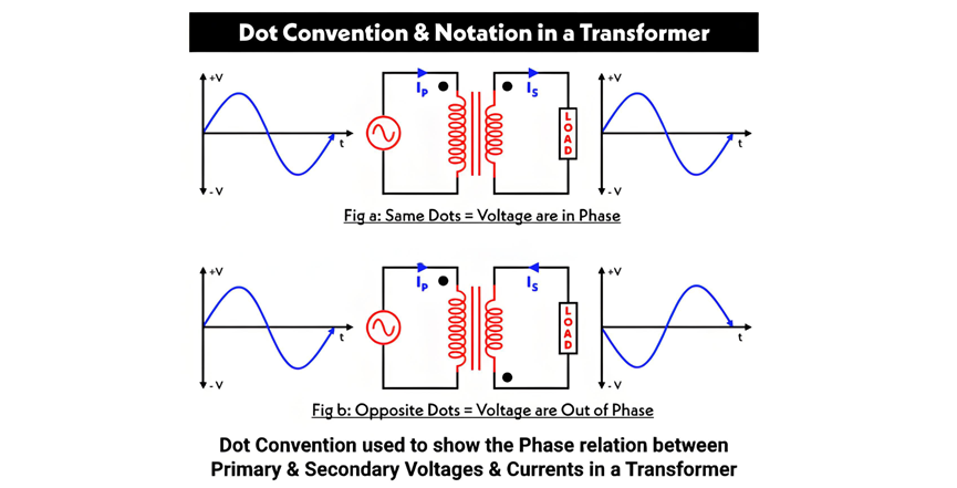
Transformer Polarity ug Dot Convention
Sa Figure A, duha ka dots gitukod sa sama nga bahin sa primary ug secondary windings. Kini nagpakita nga ang current nga mosulod sa dotted terminal sa primary winding adunay sama nga direksyon sa current nga mogawas sa dotted terminal sa secondary winding. Kasagaran, ang voltages sa dotted ends in phase—kon positive ang voltage sa dotted point sa primary, positive usab ang voltage sa dotted point sa secondary.
Sa Figure B, ang dots gisugdan sa opisito nga bahin sa windings, nagpakita nga ang windings gipasabot sa opisito nga direksyon sa core. Ania, ang voltages sa dotted points out of phase: ang positive voltage sa primary’s dotted terminal naka-correspond sa negative voltage sa secondary’s dotted terminal.
Additive vs. Subtractive Polarity
Ang transformer polarity mahimong classify isip additive o subtractive. Aron matukod kung unsa ang applicable, iconnect ang usa ka terminal sa primary winding sa usa ka terminal sa secondary winding ug ibutang ang voltmeter sa remaining terminals sa both windings.
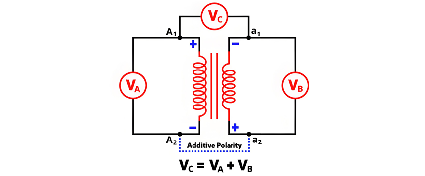
Additive Polarity

The circuit diagram of additive polarity is shown in the figure below.
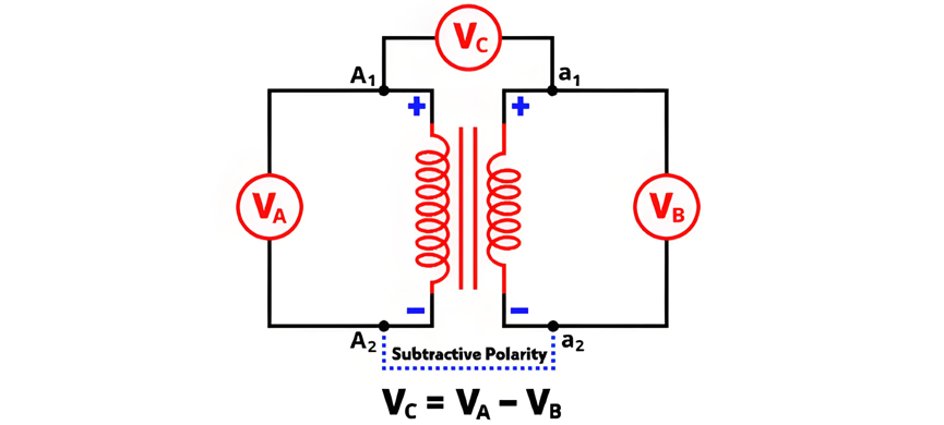
In subtractive polarity, the voltmeter measures the difference between the primary voltage and the secondary voltage. Denoted as VC, the voltmeter reading is expressed by the equation:

The circuit diagram of subtractive polarity is shown in the figure below.
Circuit Diagram of Polarity Test
The circuit diagram of the polarity test is shown in the figure below.
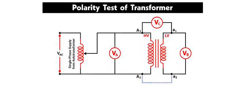
Polarity Testing of Transformers
The primary winding terminals are denoted as A1, A2, and the secondary winding terminals as a1, a2. As shown in the figure, a voltmeter VA is connected across the primary winding, VB across the secondary winding, and VC between the primary terminal A1 and secondary terminal a1.
An autotransformer is used to provide a variable AC supply to the primary winding. All voltmeter readings are recorded under this configuration:
Polarity Test Using a DC Source (Battery)
The AC voltage method described above can be impractical for determining the relative polarity of two-winding transformers. A more convenient approach uses a DC source (battery), a switch, and a DC permanent-magnet voltmeter. The connection diagram for this method—including the correct battery polarity—is shown in the figure below.
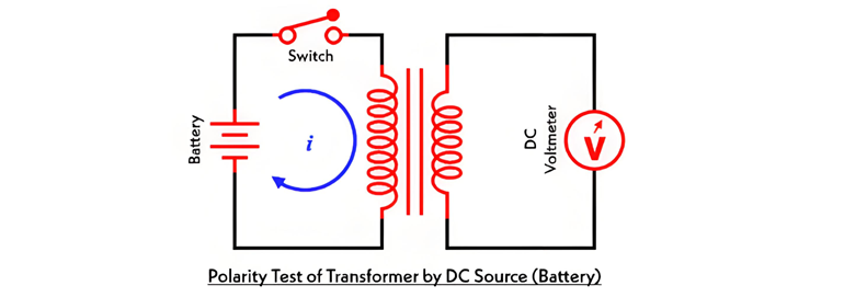
A switch is connected in series with the primary winding. When the switch is closed, the battery is connected to the primary winding, allowing current to flow through it. This generates flux linkage in both windings, inducing electromotive force (EMF) in both the primary and secondary windings.
The induced EMF in the primary winding has a positive polarity at the end connected to the battery's positive terminal. To determine the secondary winding's polarity:


