
Mafarin Yadda Ake Kula Da Turancin Mafi Tsawo A Turanci Na Zabu Biyu
A turancin mafi tsawo na zabu biyu, daya daga cikin abubuwa na karamin da yake zama mafi tsawo wajen shi ne. Mafarin yadda ake kula da turancin mafi tsawo tana nufin yadda ake kula da ingantaccen voltages bayan mafi tsawon (HV) da mafi kyau (LV). A cikin turancin mafi tsawo na yau da kullum, abubuwan da suka fi sune suna fitar da su waɗanda ake yi nasara da su, kuma mafarin yadda ake kula ta nuna hanyar da ake kula da su da kuma kayayyaki.
Mu'amala ga Mafarin Yadda Ake Kula Da Turancin Mafi Tsawo
Fahimtar mafarin yadda ake kula da turancin mafi tsawo ya shafi wajen gudanar da ayyukan da kuma ayyukan:
Kayayyakin da Mafarin Yadda Ake Kula Da Turancin Mafi Tsawo
Ya fi girma da ake amfani da kayayyakin H1/H2 don primary (HV) windings da X1/X2 don secondary (LV) windings don in nuna mafarin yadda ake kula da turancin mafi tsawo:
A lokacin da ake yi mafarin yadda ake kula da turancin mafi tsawo, wasu alamomin ya taimaka wajen:
Yadda Ake Bincika
Mafarin da ba daidai ba zai iya haifar da:
Daga ma'anar ake amfani da kayayyakin da su daidai (H1/H2 da X1/X2), engineers da technicians suka iya tabbatar da mafarin yadda ake kula da turancin mafi tsawo, wanda yake taimaka wajen a yi amfani da kuliya a cikin hankali, amincewa da kuma karkashin systemen kuliya.
Mafarin Yadda Ake Kula Da Turancin Mafi Tsawo
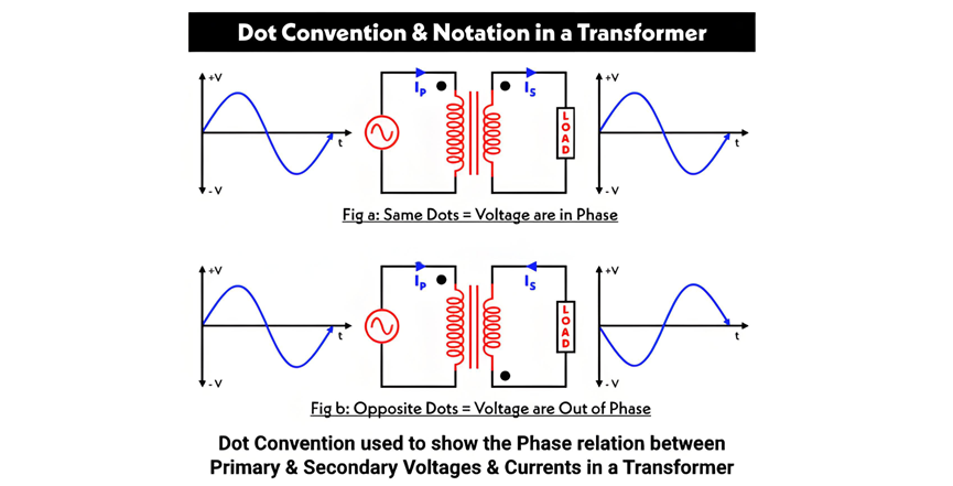
Dot convention (ko dot notation) tana da muhimmanci a cikin tarihin ake amfani don in nuna mafarin yadda ake kula da turancin mafi tsawo a cikin transformer.
Mafarin Yadda Ake Kula Da Turancin Mafi Tsawo da Dot Convention
A Figure A, an samun dots a nan darin primary da secondary windings. Wannan tana nuna cewa current da yake kula zuwa dotted terminal of the primary winding yana da hanyar daidai da current da yake kula daga dotted terminal of the secondary winding. Saboda haka, voltages a dotted ends ana in phase—idana voltage a dotted point of the primary yana da tsawo, voltage a dotted point of the secondary zai da tsawo da kuma.
A Figure B, dots suna samun a nan farkon windings, wanda tana nuna cewa windings suna kula a nan farko a nan core. A nan, voltages a dotted points ana out of phase: positive voltage a primary's dotted terminal tana nuna negative voltage a secondary's dotted terminal.
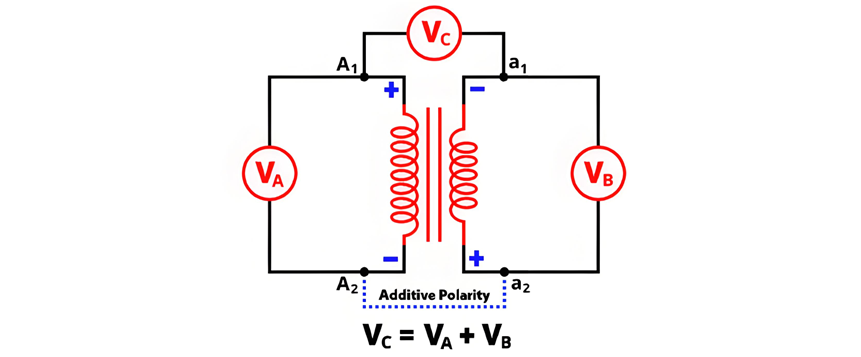
Additive vs. Subtractive Polarity
Mafarin yadda ake kula da turancin mafi tsawo tana da additin ko subtractive. Don in tabbatar da wata, ya kamata a kula terminal daya daga primary winding zuwa terminal daya daga secondary winding kuma a kula voltmeter across the remaining terminals of both windings.
Additive Polarity

Circuit diagram of additive polarity is shown in the figure below.
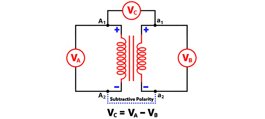
In subtractive polarity, the voltmeter measures the difference between the primary voltage and the secondary voltage. Denoted as VC, the voltmeter reading is expressed by the equation:

The circuit diagram of subtractive polarity is shown in the figure below.
Circuit Diagram of Polarity Test
The circuit diagram of the polarity test is shown in the figure below.
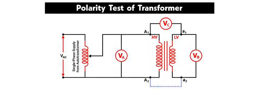
Polarity Testing of Transformers
The primary winding terminals are denoted as A1, A2, and the secondary winding terminals as a1, a2. As shown in the figure, a voltmeter VA is connected across the primary winding, VB across the secondary winding, and VC between the primary terminal A1 and secondary terminal a1.
An autotransformer is used to provide a variable AC supply to the primary winding. All voltmeter readings are recorded under this configuration:
Polarity Test Using a DC Source (Battery)
The AC voltage method described above can be impractical for determining the relative polarity of two-winding transformers. A more convenient approach uses a DC source (battery), a switch, and a DC permanent-magnet voltmeter. The connection diagram for this method—including the correct battery polarity—is shown in the figure below.
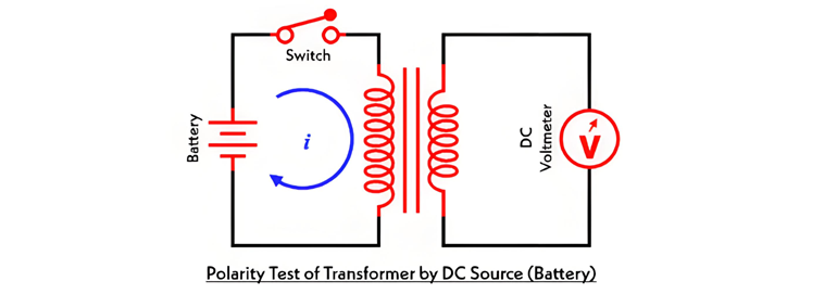
A switch is connected in series with the primary winding. When the switch is closed, the battery is connected to the primary winding, allowing current to flow through it. This generates flux linkage in both windings, inducing electromotive force (EMF) in both the primary and secondary windings.
The induced EMF in the primary winding has a positive polarity at the end connected to the battery's positive terminal. To determine the secondary winding's polarity:


