Pagsusuri sa Polarity ng Transformer – Diagrama ng Sirkuito at Paggana

Polarity sa mga Two-Winding Transformers
Sa mga two-winding transformers, ang isang terminal ng winding ay palaging positibo kumpara sa isa pa sa anumang oras. Ang polarity ng transformer ay tumutukoy sa relasyong direksyon ng induksiyon ng voltages sa pagitan ng high-voltage (HV) at low-voltage (LV) windings. Sa praktikal na mga transformer, ang mga terminal ng winding ay inilalabas bilang mga lead, at ang polarity ay nagpapahiwatig kung paano konektado at pinaglabasan ang mga ito.
Importansya ng Polarity ng Transformer
Ang pag-unawa sa polarity ay mahalaga para sa ilang operasyonal at engineering na gawain:
Markahan ng Terminal at Pagkakakilanlan ng Polarity
Kaysa sa tradisyonal na dot markings, mas malinaw na gamitin ang H1/H2 para sa primary (HV) windings at X1/X2 para sa secondary (LV) windings upang ipahayag ang polarity:
Sa panahon ng polarity testing, ang mga label na ito ay tumutulong sa pagkakakilanlan:
Pangunahing Konsiderasyon
Ang mali na polarity ay maaaring magresulta sa:
Sa pamamagitan ng pag-standardize sa malinaw na markahan ng terminal (H1/H2 at X1/X2), maaaring siguruhin ng mga engineer at teknisyan ang tamang polarity ng transformer, na nagpapataas ng kaligtasan, reliabilidad, at epektividad ng mga power systems.
Transformer Polarity
Ang dot convention (o dot notation) ay isang standard na paraan na ginagamit upang ipahayag ang polarity ng mga winding sa transformer.
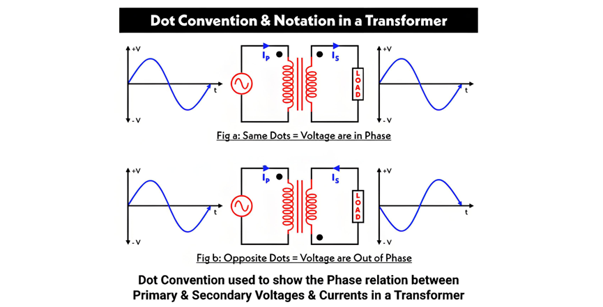
Transformer Polarity at Dot Convention
Sa Figure A, dalawang dots ang inilagay sa parehong bahagi ng primary at secondary windings. Ito ay nagpapahayag na ang current na pumasok sa dotted terminal ng primary winding ay may parehong direksyon sa current na lumabas sa dotted terminal ng secondary winding. Bilang resulta, ang voltages sa mga dotted ends ay in phase—kung ang voltage sa dotted point ng primary ay positibo, ang voltage sa dotted point ng secondary ay positibo rin.
Sa Figure B, ang mga dots ay nasa kabilang bahagi ng mga windings, na nagpapahayag na ang mga windings ay nakaroll sa kabaligtaran na direksyon sa core. Dito, ang voltages sa mga dotted points ay out of phase: ang positibong voltage sa dotted terminal ng primary ay tumutugon sa negatibong voltage sa dotted terminal ng secondary.
Additive vs. Subtractive Polarity
Ang polarity ng transformer ay maaaring classify bilang additive o subtractive. Upang matukoy kung alin ang applicable, i-connect ang isang terminal ng primary winding sa isang terminal ng secondary winding at i-attach ang voltmeter sa natitirang terminals ng parehong windings.
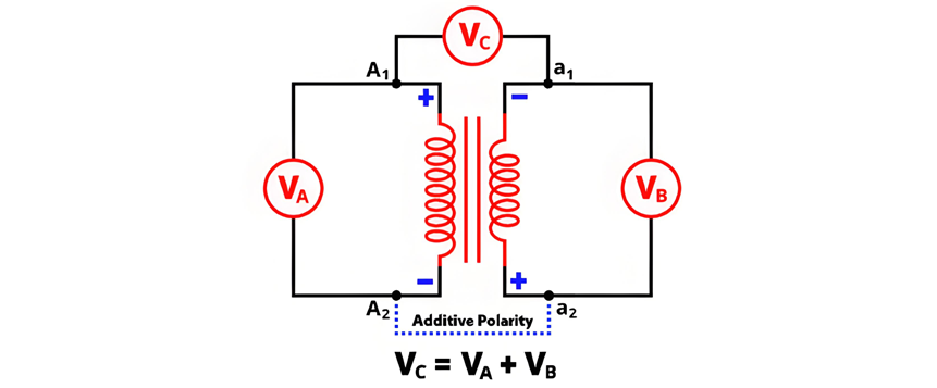
Additive Polarity

The circuit diagram of additive polarity is shown in the figure below.
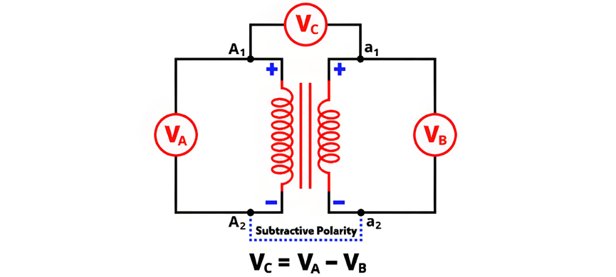
Subtractive Polarity
In subtractive polarity, the voltmeter measures the difference between the primary voltage and the secondary voltage. Denoted as VC, the voltmeter reading is expressed by the equation:

The circuit diagram of subtractive polarity is shown in the figure below.
Circuit Diagram of Polarity Test
The circuit diagram of the polarity test is shown in the figure below.
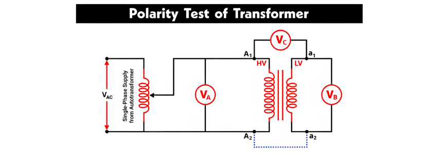
Polarity Testing of Transformers
The primary winding terminals are denoted as A1, A2, and the secondary winding terminals as a1, a2. As shown in the figure, a voltmeter VA is connected across the primary winding, VB across the secondary winding, and VC between the primary terminal A1 and secondary terminal a1.
An autotransformer is used to provide a variable AC supply to the primary winding. All voltmeter readings are recorded under this configuration:
Polarity Test Using a DC Source (Battery)
The AC voltage method described above can be impractical for determining the relative polarity of two-winding transformers. A more convenient approach uses a DC source (battery), a switch, and a DC permanent-magnet voltmeter. The connection diagram for this method—including the correct battery polarity—is shown in the figure below.
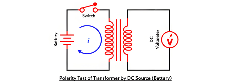
A switch is connected in series with the primary winding. When the switch is closed, the battery is connected to the primary winding, allowing current to flow through it. This generates flux linkage in both windings, inducing electromotive force (EMF) in both the primary and secondary windings.
The induced EMF in the primary winding has a positive polarity at the end connected to the battery's positive terminal. To determine the secondary winding's polarity: