Fault Analysis and Troubleshooting of High-Voltage Vacuum Circuit Breakers
The advantages of vacuum circuit breakers go beyond oil-free design. They also offer long electrical and mechanical life, high dielectric strength, strong consecutive breaking capacity, compact size, light weight, suitability for frequent operation, fire prevention, and low maintenance—benefits quickly recognized by power system operators, maintenance personnel, and engineers. Early domestically produced high-voltage vacuum circuit breakers in China suffered from unstable quality, excessive current chopping overvoltage during operation, and occasional vacuum interrupter leakage.
However, by the 1992 Tianjin Vacuum Switch Application Promotion Conference, China’s vacuum circuit breaker manufacturing technology had advanced to the international forefront, marking a turning point in its application and development. With the widespread use of vacuum circuit breakers, failures occasionally occur. This article analyzes common faults and provides corresponding solutions.
Common Abnormal Operating Conditions
1. Circuit Breaker Fails to Close or Open (Refusal to Operate):After receiving a close (or trip) command, the closing (or tripping) solenoid operates, the plunger releases the latch, and the closing (or opening) spring releases energy to drive the mechanism. However, the interrupter fails to close (or open).
2. Unintended Tripping (False Tripping):The breaker trips without any external control signal or manual operation during normal service.
3. Storage Motor Continues Running After Spring Charging:After closing, the motor starts charging the spring. Even after full energy storage, the motor continues running.
4. Increased DC Resistance:After extended operation, the contact resistance of the vacuum interrupter’s contacts gradually increases.
5. Increased Closing Bounce Time:Over time, the duration of contact bounce during closing increases.
6. Discharge from CT Surface to Support Bracket in Middle Chamber:During operation, arcing occurs between the current transformer (CT) surface and the support structure in the middle chamber.
7. Vacuum Interrupter Fails to Open:After a trip command, the interrupter fails to open or opens only partially (single-phase or two-phase operation).

Fault Cause Analysis
1. Refusal to Close or Open
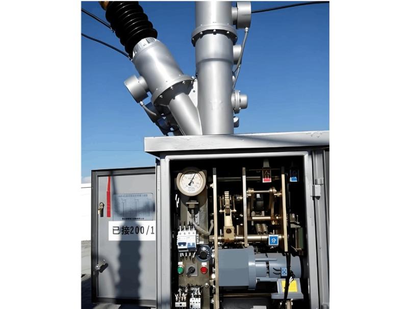
When the operating mechanism fails to actuate, first determine whether the cause is in the secondary control circuit (e.g., protection relay) or mechanical components. After confirming the secondary circuit is normal, excessive clearance in the universal joint connecting the main lever arm of the mechanism was found. Although the mechanism operates normally, it fails to drive the linkage, resulting in failed closing or tripping.
2. Unintended Tripping
In normal operation, the breaker should not trip without an external command. After ruling out human error, inspection revealed a short circuit at the auxiliary switch contacts inside the mechanism box. The trip coil was energized through this short, causing false tripping. The root cause was rainwater ingress into the mechanism box, flowing down the output crank arm and directly onto the auxiliary switch, causing contact shorting.
3. Storage Motor Continues Running After Spring Charging
After closing, the energy storage motor starts. When the spring is fully charged, a signal indicates completion. The storage circuit includes a normally open auxiliary contact from the breaker and a normally closed limit switch contact. After closing, the auxiliary contact closes, starting the motor. Once the spring is fully charged, the mechanism lever opens the limit switch’s normally closed contact, cutting power to the motor. If the lever fails to open this contact, the circuit remains energized, and the motor continues running.
4. Increased DC Resistance
Vacuum interrupter contacts are butt-type. Excessive contact resistance causes overheating under load, impairing conductivity and interrupting performance. Resistance must remain below manufacturer specifications. Contact spring pressure significantly affects resistance and must be measured under proper overtravel conditions. Gradually increasing resistance reflects contact erosion. Contact wear and changes in contact gap are the primary causes of rising DC resistance.
5. Increased Closing Bounce Time
Some contact bounce is normal during closing, but excessive bounce can cause contact burning or welding. The technical standard limits closing bounce to ≤2ms. Over time, the main causes of increased bounce are reduced contact spring force and wear-induced clearance in levers and pins.
6. Discharge from CT Surface to Support Bracket
The middle chamber houses a current transformer (CT). During operation, uneven electric fields can form on the CT surface. To prevent this, manufacturers coat the surface with semiconductor paint to equalize the field. During assembly, space constraints may cause the semiconductor coating around mounting bolts to be scraped off, leading to field distortion and surface-to-bracket discharge during operation.
7. Vacuum Interrupter Fails to Open
Under normal conditions, the breaker should reliably interrupt current whether tripped manually or by protection relay.
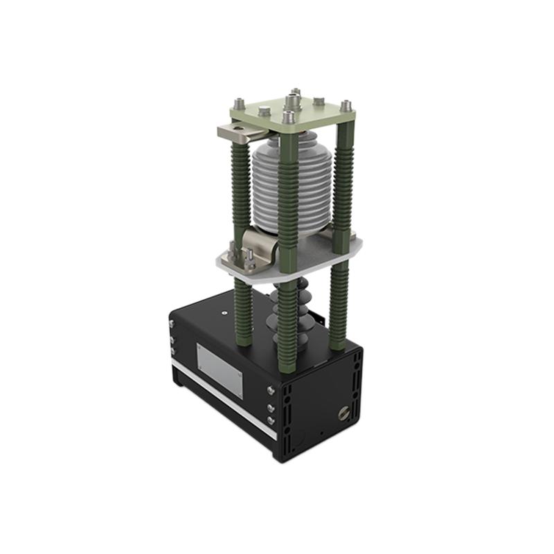
Vacuum circuit breakers differ from other types by using vacuum as both insulation and arc-quenching medium. If the vacuum level drops, ionization occurs inside the chamber, generating charged particles that reduce insulation strength, preventing proper current interruption.
Troubleshooting and Solutions
1. Refusal to Close or Open:Inspect all connecting parts in the operating mechanism for excessive clearance. Replace worn components with new, high-hardness, qualified parts.
2. Unintended Tripping:Seal all potential rain entry points; install protective silicone sleeves on the output crank linkage; activate the heating and moisture-removal device inside the mechanism box.
3. Storage Motor Continues Running After Spring Charging:Adjust the position of the limit switch so that the lever fully opens its normally closed contact when the spring is fully charged.
4. Increased DC Resistance:Adjust the contact gap and overtravel of the interrupter. Measure contact resistance using the DC voltage drop method (with test current ≥100A) as specified in standards. If adjustment fails to reduce resistance, replace the vacuum interrupter.
5. Increased Closing Bounce Time:Slightly increase the initial pressure of the contact spring or replace it. If lever or pin clearance exceeds 0.3mm, replace these parts. Adjust the drive mechanism by shifting it slightly toward the dead center point in the closed position—where transmission ratio is minimal—to reduce bounce.
6. Discharge from CT Surface to Support Bracket:Evenly reapply a layer of semiconductor paint on the CT surface to restore uniform electric field distribution.
7. Vacuum Interrupter Fails to Open
If vacuum integrity is confirmed below required levels, replace the vacuum interrupter. Follow these steps:
Ensure the new vacuum interrupter passes vacuum integrity testing before installation.
Remove the old interrupter and install the new one vertically. Ensure alignment between the moving contact rod and the interrupter. Avoid torsional stress during installation.
After installation, measure contact gap and overtravel. Adjust as needed:① Adjust overtravel via the insulating pull rod’s threaded connection.② Adjust contact gap by modifying the length of the moving conductive rod.
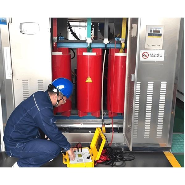
Use a circuit breaker analyzer to measure opening/closing speed, three-phase synchronization, and closing bounce. Make further adjustments if results are out of specification.


