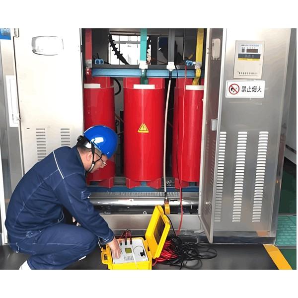
Kurçkerên Çerîna Vakûm: Sêbêj û Rewşên Cilkirina Wan

Vekilîkirina û Xebitandina Karkirên Dûrêkên Vacûmî ya Ji Bêtir
Zynendîyên dûrêkên vacûmî di hêsan de jî ber bi projeyên bê neftan. Yana da jî çi azîn jiyanî û makînîkî dereng, qewa dielektrîkî yekbû, kawetina bikarhastina seriyê, mezûn e, kelepikî, wekî ji bo karkeşan pêk, pelengîna ewle, û bêparzûnayî - zynendîyên ku çawn di dema xwe de taybetandin wan biguherînin yên bikarhastina rêzeyî, perkarên parzûnayî, û mühendisan. Dûrêkên vacûmî ji bêtir yên din bikinra li Çîn ê destpêk da ku çavkanîya nist, piştî operasyonê overvoltageya current choppingê gir, û herêmîn da ku çavkaniyên interrupterê vacûmî.
Lê, ji bo Konferansê Promotyonê Bikara Switchê Vacûmî Tianjin ê li sâl 1992, teknolojîya bikinra dûrêkên vacûmî ya Çîn vê biçûka wergerî yên ji bo navbera navendî, ku bi vê rêya vêguh dikin. Bi bikaranîna geze û pêşder dûrêkên vacûmî, yan jî kerkirên çawn hatine. Vê nivîsê analîz di karûbarên herêmîn de kiribû û çarekên tevahî yên parzûneyê pêşke hatine.
Mînakên Serbestî yên Operasyon
1. Dûrêka Nekatîne Li Ber (An Jî) Li Der (Refusal to Operate): Piştî derketina komanda li ber (an jî li der), solenoida li ber (an jî li der) operasyonê kiribû, plunger lêser rastan, û resorte li ber (an jî li der) energya pêşke werdigire ku mekanizma birêve. Lê, interrupter nakekatîne li ber (an jî li der).
2. Tripping Mistî (False Tripping): Dûrêka li der dibû, ji bo ku tune komanda kontrolê derveyî an operasyonê bikarhêner û di dema xwe de.
3. Motor Storage Da Bike Dibe Piştî Spring Charging:Piştî li ber kirina, motor charging springê destpêkiribû. Jî bo full energy storage, motor bike dibû.
4. Zêdetirina Rezîstansa DC:Piştî operasyonê derdî, rezîstansa contactan de vacuum interrupterê zêdetir dibû.
5. Zêdetirina Demê Bounce Closing:Derdemê, demê bounce closing zêdetir dibû.
6. Discharge Ji Surface CT Brackets Support Middle Chamber:Di dema operasyonê de, arcing di surface CT û support structure de middle chamber dibû.
7. Vacuum Interrupter Nekatîne Li Der:Piştî komanda trip, interrupter nakekatîne li der an jî li der bike dibû (operasyona phase yekan an du).

Analîzê Sabeqê Fault
1. Refusal to Close or Open
Ji bo ku mechanisma bikarhastina nakebatî, yekemîn biafirînin ku sabeb di circuit control secondary (mînacegir relay) an components mechanical de ye. Piştî destnîşan circuit secondary normal e, gap universal joint connecting main lever arm mechanisma pir girt. Mechanisma operasyonê normal dikir, lê nakebatîne linkage drive, ku nakekatîne li ber an jî li der.
2. Unintended Tripping
Di dema xwe de, breaker nakebatîne li der bi komanda derveyî. Piştî human error ruled out, inspection revealed a short circuit at the auxiliary switch contacts inside the mechanism box. Trip coil energized through this short, causing false tripping. The root cause was rainwater ingress into the mechanism box, flowing down the output crank arm and directly onto the auxiliary switch, causing contact shorting.
3. Storage Motor Continues Running After Spring Charging
Piştî li ber, motor storage start. When the spring is fully charged, a signal indicates completion. The storage circuit includes a normally open auxiliary contact from the breaker and a normally closed limit switch contact. Pištî li ber, auxiliary contact closes, starting the motor. Once the spring is fully charged, the mechanism lever opens the limit switch’s normally closed contact, cutting power to the motor. If the lever fails to open this contact, the circuit remains energized, and the motor continues running.
4. Increased DC Resistance
Contacts vacuum interrupter are butt-type. Excessive contact resistance causes overheating under load, impairing conductivity and interrupting performance. Resistance must remain below manufacturer specifications. Contact spring pressure significantly affects resistance and must be measured under proper overtravel conditions. Gradually increasing resistance reflects contact erosion. Contact wear and changes in contact gap are the primary causes of rising DC resistance.
5. Increased Closing Bounce Time
Some contact bounce is normal during closing, but excessive bounce can cause contact burning or welding. The technical standard limits closing bounce to ≤2ms. Over time, the main causes of increased bounce are reduced contact spring force and wear-induced clearance in levers and pins.
6. Discharge from CT Surface to Support Bracket
The middle chamber houses a current transformer (CT). During operation, uneven electric fields can form on the CT surface. To prevent this, manufacturers coat the surface with semiconductor paint to equalize the field. During assembly, space constraints may cause the semiconductor coating around mounting bolts to be scraped off, leading to field distortion and surface-to-bracket discharge during operation.
7. Vacuum Interrupter Fails to Open
Under normal conditions, the breaker should reliably interrupt current whether tripped manually or by protection relay.
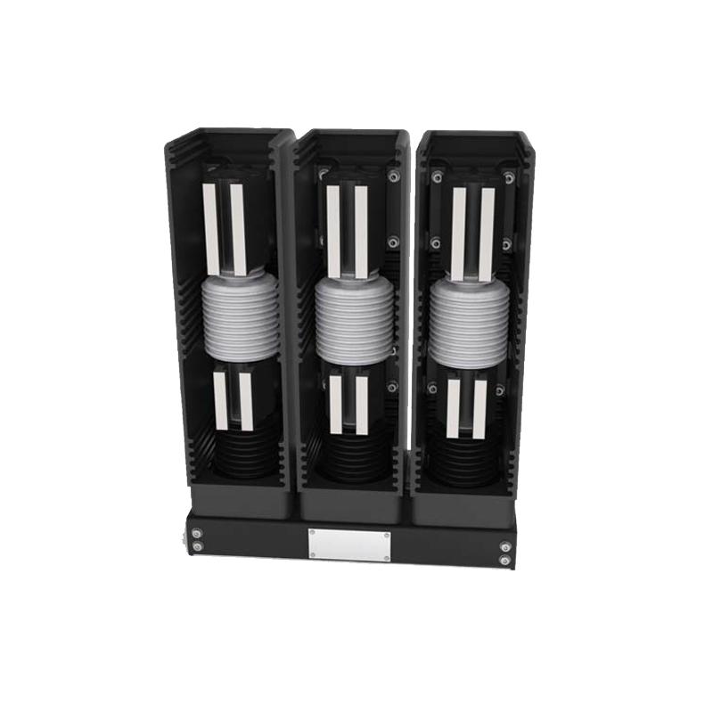
Vacuum circuit breakers differ from other types by using vacuum as both insulation and arc-quenching medium. If the vacuum level drops, ionization occurs inside the chamber, generating charged particles that reduce insulation strength, preventing proper current interruption.
Troubleshooting and Solutions
1. Refusal to Close or Open:Inspect all connecting parts in the operating mechanism for excessive clearance. Replace worn components with new, high-hardness, qualified parts.
2. Unintended Tripping:Seal all potential rain entry points; install protective silicone sleeves on the output crank linkage; activate the heating and moisture-removal device inside the mechanism box.
3. Storage Motor Continues Running After Spring Charging:Adjust the position of the limit switch so that the lever fully opens its normally closed contact when the spring is fully charged.
4. Increased DC Resistance:Adjust the contact gap and overtravel of the interrupter. Measure contact resistance using the DC voltage drop method (with test current ≥100A) as specified in standards. If adjustment fails to reduce resistance, replace the vacuum interrupter.
5. Increased Closing Bounce Time:Slightly increase the initial pressure of the contact spring or replace it. If lever or pin clearance exceeds 0.3mm, replace these parts. Adjust the drive mechanism by shifting it slightly toward the dead center point in the closed position—where transmission ratio is minimal—to reduce bounce.
6. Discharge from CT Surface to Support Bracket:Evenly reapply a layer of semiconductor paint on the CT surface to restore uniform electric field distribution.
7. Vacuum Interrupter Fails to Open
If vacuum integrity is confirmed below required levels, replace the vacuum interrupter. Follow these steps:
Ensure the new vacuum interrupter passes vacuum integrity testing before installation.
Remove the old interrupter and install the new one vertically. Ensure alignment between the moving contact rod and the interrupter. Avoid torsional stress during installation.
After installation, measure contact gap and overtravel. Adjust as needed: ① Adjust overtravel via the insulating pull rod’s threaded connection. ② Adjust contact gap by modifying the length of the moving conductive rod.
Use a circuit breaker analyzer to measure opening/closing speed, three-phase synchronization, and closing bounce. Make further adjustments if results are out of specification.