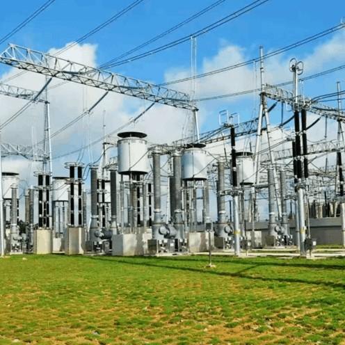
1 Failure Mechanisms of Power Capacitors
A power capacitor primarily consists of a housing, capacitor core, insulating medium, and terminal structure. The housing is typically made of thin steel or stainless steel, with bushings welded to the cover. The capacitor core is wound from polypropylene film and aluminum foil (electrodes), and the interior of the housing is filled with liquid dielectric for insulation and heat dissipation.
As a fully sealed device, common failure types of power capacitors include:
Internal capacitor element breakdown;
Fuse blowing;
Internal short-circuit faults;
External discharge faults.
Internal failures are more destructive to the capacitor body and, once occurred, generally cannot be repaired on-site, significantly affecting equipment utilization efficiency.
1.1 Internal Capacitor Element Breakdown
Capacitor element breakdown is primarily caused by factors such as dielectric aging, moisture ingress, manufacturing defects, and harsh operating conditions. If the element lacks an internal fuse, a single element breakdown will short-circuit its parallel-connected counterparts, removing them from voltage sharing. This increases the operating voltage across the remaining series-connected elements. Without timely fault isolation, this poses serious safety risks and may lead to catastrophic failures.The use of internal fuses enables effective and prompt isolation of faulty elements, enhancing operational safety.
Capacitor breakdown can be classified into three types: electrical breakdown, thermal breakdown, and partial discharge breakdown.
Electrical Breakdown: Caused by overvoltage or harmonics, leading to excessively high electric field strength across the dielectric, resulting in insulation failure at defective points. It is characterized by short duration and high field intensity. Breakdown strength is closely related to field uniformity but less sensitive to temperature and voltage duration.
Thermal Breakdown: Occurs when heat generation exceeds dissipation, causing continuous temperature rise in the dielectric, leading to material degradation and eventual insulation failure. This typically happens during steady-state operation, with relatively lower breakdown voltage and longer voltage application time compared to electrical breakdown.
Partial Discharge Breakdown: Results from localized high electric fields within the dielectric, exceeding the breakdown strength of low-permittivity regions such as liquids, gases, or impurities. This initiates partial discharges that gradually degrade insulation performance, eventually evolving into a complete through-electrode breakdown. The process is progressive, developing from non-penetrating discharges to full insulation failure.
1.2 Fuse Blowing
Fuse protection is one of the most common protective measures for power capacitors and plays a vital role in the safe and stable operation of compensation systems. It is categorized into external and internal fuse protection.
External Fuse Protection: When an internal capacitor element fails, the fault current through the capacitor and external fuse increases. Once the current reaches the fuse’s rated melting threshold, the fuse heats up, breaks thermal equilibrium, and melts, disconnecting the faulty capacitor to prevent fault escalation.
Internal Fuse Protection: Upon element failure, parallel elements discharge into the faulted element, generating a high-amplitude, rapidly decaying transient current. The energy from this current melts the series-connected internal fuse, isolating the faulty element and allowing the rest of the capacitor to continue operating.
In practice, improper fuse selection or poor terminal contact may cause abnormal fuse blowing during normal operation, mistakenly removing healthy capacitors and reducing reactive power output.
If internal fuses are improperly sized and fail to isolate faults promptly, the fault may worsen, potentially leading to capacitor explosion or fire.
1.3 Internal Short-Circuit Faults
Internal short-circuit faults in power capacitors mainly include live electrode-to-housing shorts and inter-electrode shorts. These are primarily caused by long-term dielectric aging, internal moisture ingress, overvoltage stress, or inherent insulation defects from design or manufacturing processes, all of which can lead to puncture-type insulation breakdown and internal short circuits.
1.4 External Discharge Faults
External discharge faults refer to failures occurring outside the capacitor body, caused by external factors such as bushing surface flashover, bushing puncture, phase-to-phase or phase-to-ground short circuits, or cracks in porcelain bushings due to mechanical stress. These faults have diverse causes but occur in the external circuitry. They can generally be detected and mitigated in time through relay protection actions, routine inspections, or offline testing. Their occurrence probability and severity are lower than internal faults, yet they still warrant sufficient attention.
2 Common Fault Characteristics and Causes of Power Capacitors
2.1 Oil Leakage from Capacitor Body
As a fully sealed, high-field-strength, high-current device, oil leakage in a power capacitor not only reduces insulation level due to lowered oil level but also allows moisture ingress due to decreased internal pressure. This leads to insulation dampness, reduced insulation resistance, and ultimately internal element breakdown or even explosion.
Main causes of oil leakage include: poor welding leading to inadequate sealing; aging or unevenly stressed gaskets; mechanical damage during transportation or installation; inadequate maintenance causing housing corrosion; and mechanical stress damaging bushing seals.
2.2 Capacitor Housing Deformation
Under normal operating conditions, minor expansion or contraction of the capacitor housing due to temperature and voltage variations is acceptable. However, when internal electric field strength is excessive, causing partial discharge or short circuits, the dielectric decomposes and generates large amounts of gas. This increases internal pressure in the sealed chamber, leading to housing bulging or deformation.
Once severe deformation occurs, on-site repair is usually impossible, and replacement is required. Housing deformation not only exacerbates internal insulation deterioration but may also damage the electrical structure, altering original insulation clearances. In severe cases, it can cause bushing fracture (see Fig. 1), potentially leading to explosion or fire.
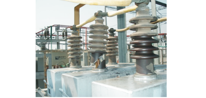
Housing deformation is primarily caused by product quality issues, such as: poor electrode or dielectric material quality; use of non-gas-absorbing insulating oil; substandard manufacturing environment or processes; residual impurities during production; excessive pursuit of specific performance metrics; or housing material being too thin.
2.3 Abnormal Temperature Rise in Capacitors
An abnormal temperature rise in power capacitors leads to excessive body temperature, which accelerates thermal aging of the internal dielectric, reduces its insulation strength, and may even trigger partial discharge. The service life of power capacitors generally follows the "8°C rule": for every 8°C increase above the design-allowed operating temperature, the expected lifespan is approximately halved.
Abnormal temperature rise is primarily caused by poor ventilation or prolonged overcurrent conditions. Examples include: unreasonable spatial layout of the capacitor room or improper placement of ventilation equipment leading to inadequate heat dissipation; increased heating due to overvoltage operation causing overcurrent; and harmonic currents generated by rectifier units that also contribute to capacitor overheating. Additionally, dielectric aging, moisture ingress, or internal component faults can increase power losses, further exacerbating temperature rise.
2.4 Surface Flashover Discharge on Capacitor Bushings
Components in power capacitor installations are typically arranged compactly. During operation, the surrounding environment features high temperature and electric field intensity, making it easy for airborne charged particles to be adsorbed. This leads to contamination buildup on bushing surfaces, increasing surface leakage current. Under the combined influence of system harmonics and voltage, localized surface arcing may occur on the bushing porcelain. When contamination accumulates to a critical level, it can result in surface flashover discharge, accompanied by abnormal noise. In severe cases, this may lead to external phase-to-ground short circuits.
2.5 Abnormal Noise from Capacitors
Power capacitors are static reactive compensation devices without moving parts or electromagnetic excitation components. Under normal operation, they should produce no audible sound. If abnormal noise occurs during operation, it may indicate high-energy partial discharge within the capacitor, and the equipment should be immediately de-energized for inspection.
2.6 Capacitor Rupture
Capacitor rupture is a severe failure with significant consequences. It typically occurs when an internal capacitor element suffers inter-electrode or electrode-to-housing insulation breakdown, resulting in a through-fault short circuit. Other capacitors operating in parallel will then rapidly charge and discharge into the faulty unit. If the injected energy exceeds the mechanical strength of the housing, the capacitor may rupture and eject oil, potentially causing fire, endangering the safety of the entire substation, and even leading to personnel injuries or fatalities.
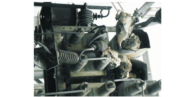
A cascading rupture incident involving an entire capacitor bank is shown in Figure 2, triggered by internal capacitor element breakdown; the detailed condition of the failed element is illustrated in Figure 3.
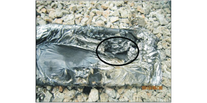
2.7 Overheating of Capacitor Bank Connection Terminals
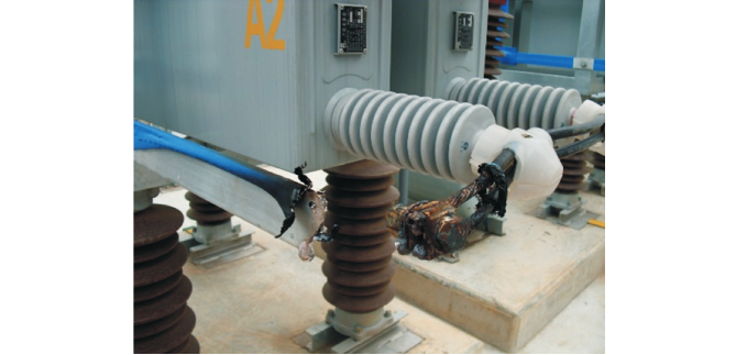
Once energized, power capacitor banks operate under full load with high circuit currents. If internal connections exhibit poor contact, inadequate design or installation practices, or insufficient maintenance, localized overheating at the connection points may occur. Prolonged overheating can lead to excessive thermal energy accumulation, potentially causing the connecting conductors to melt. Overheating faults at capacitor bank terminals are relatively common; the condition of a melted connection is shown in Figure 4.
3 Preventive Measures Against Accidents
3.1 Ensuring Quality in Equipment Manufacturing and Installation Commissioning
The safe operation of power capacitors hinges on the quality of equipment manufacturing and installation commissioning. During production, it is essential to strictly follow process flows, use qualified raw materials and production equipment, and enhance quality supervision throughout the process. Rigorous factory inspections ensure product quality. On-site installations should be reasonably "phased and grouped" to ensure balanced capacitance matching between phases and sections. Additionally, emphasis should be placed on site handover and acceptance after installation to guarantee installation quality and minimize faults during operation.
3.2 Improving Operation and Running Methods
When performing power-on and power-off operations for line loads, capacitor banks must adhere to the principle of "disconnect first, then connect," while load lines should follow the sequence of "connect first, then disconnect." This order cannot be arbitrarily changed.
Before restoring capacitor bank operations, sufficient discharge time must be ensured. Frequent switching of capacitor banks should be minimized; only after complete discharge can re-closing occur. If a fault causes protective devices to trip the capacitor bank, it cannot be reconnected before identifying the cause to prevent an accident from escalating.
To avoid high-order harmonics affecting capacitor banks, select appropriate reactor rates based on specific application scenarios. This effectively suppresses high-order harmonics, reduces inrush currents and overvoltage upon closing, ensuring safe operation of the entire system.
3.3 Controlling Operating Environment Temperature
The operational temperature of capacitors directly impacts their performance and lifespan. High temperatures accelerate insulation aging, shortening service life. Therefore, controlling the operating environment temperature is crucial. Indoor-installed capacitor banks should maintain good ventilation and, where necessary, install automatic temperature control systems. Outdoor units should avoid direct sunlight exposure and ensure proper ventilation and heat dissipation. Regularly perform live infrared thermography on capacitor banks and associated equipment to take timely measures, ensuring internal medium temperatures and environmental temperatures comply with regulations.
3.4 Implementing Online Monitoring of Equipment Operational Status
Installing online monitoring devices on capacitor banks facilitates real-time monitoring of operational status, aiding in the prompt detection and handling of potential faults. This includes monitoring actual operating voltage, partial discharges, dielectric loss, capacitance, leakage current, and other characteristic signals. Not only does this help in diagnosing and isolating faults, but it also enables analysis of potential defects, achieving predictive fault warnings.
3.5 Enhancing Routine Inspection of Equipment
Strengthening routine inspection is vital for ensuring normal operation of capacitor banks. Focus should be placed on checking for deformations in casing, oil leaks, contamination levels of porcelain insulators, signs of discharge, electrical distances, and environmental temperatures. Auxiliary methods such as infrared thermography can detect overheating at connections, enabling timely maintenance and ensuring safe operation of power capacitor assemblies.
Conclusion
By analyzing the failure mechanisms, characteristics, and causes of power capacitors, this article proposes preventive measures from five aspects: equipment and installation commissioning quality, operation methods, control of operating environment temperature, online monitoring of running conditions, and routine inspections. These recommendations provide practical guidance for the effective application of power capacitors.


