Taking the circuit breaker racking handle length of 125mm as an example, and a typical racking/unracking force of 260N, the calculation is 260 × 0.125 = 32.5 N·m. The maximum force of 400N corresponds to 400 × 0.125 = 50 N·m.
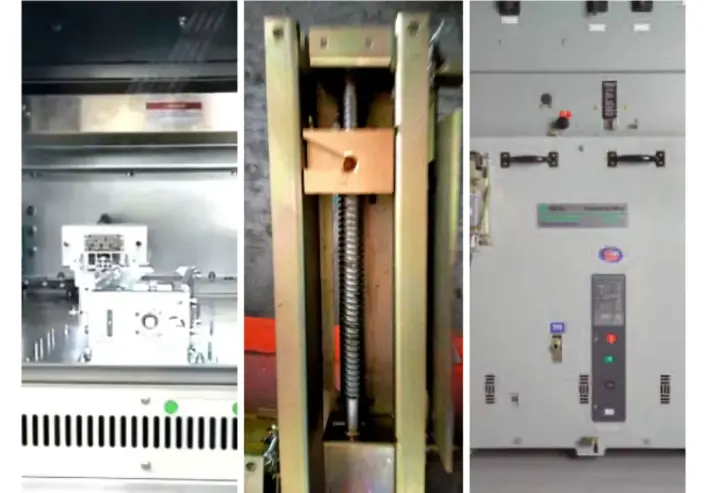
The aluminum alloy lead screw provides significant thrust. The key factor is the mechanical strength of the rear fixed crossbeam. In early mid-mounted switchgear, due to poor coordination and insufficient mechanical strength—especially in wider switchgear cabinets—the crossbeam was subjected to central loading, frequently leading to deformation. After deformation, the interlocks and operation of the racking mechanism were affected; for example, after the circuit breaker truck reached the disconnected position, the side locking plates could not be withdrawn.
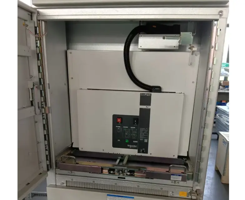
To achieve high current ratings and reduce contact heating, it is necessary to increase the contact pressure to minimize temperature rise. In North American switchgear, current transformers are installed on the bushing (contact box), requiring a smaller diameter for the tulip contacts. Since the number of contact fingers cannot be increased significantly, the contact pressure must be increased, which consequently requires a higher racking thrust.
Therefore, North American switchgear generally does not use the chassis truck form to enhance thrust and mechanical strength. By increasing contact pressure and reducing the contact outer diameter, core-type (toroidal) low-voltage current transformers can be conveniently installed in the bushing without increasing the overall dimensions.
Using dual lead screws on both sides for even load distribution can improve strength and thrust. The screws advance synchronously, ensuring even force distribution and preventing lateral tilting, which could cause jamming or unbalanced opening/closing of the shutters.
Similarly, adopting a bottom-fixed lead screw configuration prevents the fixed crossbeam from deforming. The bottom lead screw mechanism is fixed to the base plate bracket and features an integrated design with the truck's auxiliary switches, mechanical position indicator, secondary plug, and grounding contacts, ensuring high precision and excellent strength.
Block-type contact fingers have a high current-carrying capacity per unit, meaning fewer fingers are needed, resulting in lower friction. Increasing the contact spring pressure reduces contact heating. Block-type fingers provide near surface contact, improving contact efficiency. Calculations show contact coefficients of 0.5 for point contact, 0.75 for line contact, and 0.9 for surface contact. Therefore, under the same pressure, the contact resistance is significantly lower.
Block-type fingers eliminate the scratches on the static contact caused by the tips of leaf-type fingers and reduce points of excessive local pressure on the static contact surface. By increasing the contact pressure, the degree of sliding friction on the static contact is minimized.
Subject to installation constraints, the outer diameter of the tulip contact should be as small as possible. This increases the air gap between the tulip contact and the inner surface of the bushing, preventing insulation failure caused by excessive local electric field strength. The design of the contact connection system, especially for 3000A/4000A switchgear, requires a balance of insulation, temperature rise, and dynamic/thermal stability.

 Login