Kirchhoff’s Current Law

Rabert T
03/10/2024

WechatIMG1389.jpeg

Kirchhoff’s Laws include two fundamental principles in electrical circuit analysis:

  • Kirchhoff’s Current Law (KCL) (Kirchhoff’s First Law or Kirchhoff’s 1st Law) & 

  • Kirchhoff’s Voltage Law (KVL) (Kirchhoff’s Second Law or Kirchhoff’s 2nd Law).

These principles serve as essential tools for evaluating complicated electrical circuits, allowing engineers & researchers to predict & comprehend the behavior of circuits in various configurations. Kirchhoff’s Laws are widely applied in

  • Electronics engineering, 

  • Electrical engineering, &

  • Physics for circuit analysis & design.

What does Kirchhoff’s Current Law (KCL) State?

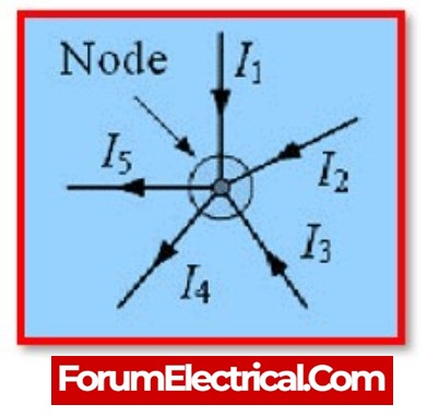
Kirchhoff’s current law states that the algebraic sum of current entering into a node (or) a loop must be equal to the algebraic sum of current flowing out of it.


Kirchhoffs-Current-Law-4.jpeg


WechatIMG1390.jpeg


What is Node?

A node is a junction, connector, or terminal in a circuit that connects two or more branches by joining or connecting circuit components. A dot represents a node.

In an electrical circuit, the term “Node” typically refers to

the joining or intersecting of two or more components, such as cables, that conduct current. A closed circuit path is also necessary for current to flow through a node, either in or out.

According to the node currents from the above diagram,

The 3 currents entering the node in this case,

  • I1, I2, and I3 all have positive values, whereas

  • I4 and I5 have negative values,

the two currents leaving the node.

As a result, the equation can also be rewritten,


Kirchhoffs-Current-Law-3.jpeg


WechatIMG1391.jpeg


What is the other name of Kirchhoff’s Current Law?

Kirchhoff’s Current Law is also called as Kirchhoff’s First Law.

Application of KCL:

KCL is used to calculate the amount of current passing through each electronic component in a circuit. By adjusting the component’s resistance, we can alter the component’s current according to KCL law.

Statement: Respect the original, good articles worth sharing, if there is infringement please contact delete.

Rabert T

As an electrical engineer with 5 years of experience, I focus on transformer and circuit breaker reliability in 110/33-11kV and 33/11kV substations. I am a professional electrical engineer with experience in transformer service and maintenance.

Electrical And Electronic Symbols
An electrical symbol is a small image used to represent an electrical or electronic device or function. They are also known as circuit symbols or schematic symbols as they are used in electrical schematics and diagrams.Some basic electrical symbols include: Wires Diode Batteries Transformers Capacitors Resistors Inductors Fuses Switches Bipolar Junction Transistors Electromagnetic RelaysThere are many electrical and circuit symbols used internationally around the world. While they are mostly st
Blake
03/18/2024
Electrical Transformers – Formulas and Equations
Transformers are one of the most common types of electrical devices, and they may be found in a variety of applications within the area of electrical engineering, including power systems. Therefore, in the position of an electrical engineer, it is usually neededto compute various characteristics of a transformer in order to establish the circumstances under which it operates. In order to do this,will need to use conventional equations, which can be seen mentioned in the sections that will follow
Hobo
03/18/2024
Lenz's Law Explained
Lenz's Law, named after the Russian physicist Heinrich Lenz (1804-1865), is a fundamental principle in electromagnetism. It states that the direction of the induced electromotive force (emf) in a closed conducting loop always opposes the change in magnetic flux that caused it. This means that the induced current creates a magnetic field that opposes the initial change in magnetic flux, following the principles of conservation of energy.Understanding Lenz's Law allows us to appreciate the science
The Electricity Forum
03/18/2024
What is Shunt Resistor and How Does it Work?
In several electrical and power applications, the measurement of current flow is essential.Hence, current measurement is commonly required for monitoring and controlling applications.Depending on the kind of application, many types of current sensors with specialised current sensing technologies are available to detect (or)measure current flow.A current sensing resistor, also known as a shunt resistor, is the most prevalent methodto measure current flow in any application.This postdescribes shun
Rabert T
03/12/2024
Inquiry
Download
IEE-Business is dedicated to serving the personnel in the global power industry.
Join IEE-Business, not only can you discover power equipment and power knowledge, but also canhnd like - minded friends!