• Product
  • Suppliers
  • Manufacturers
  • Solutions
  • Free tools
  • Knowledges
  • Experts
  • Communities
Search


What Is the Fast Verification Wiring Method for Low-Voltage Current Transformers?

Oliver Watts
Oliver Watts
Field: Inspection and testing
China

To ensure safe operation of the power system, power equipment operation must be monitored/measured. General devices can’t connect to primary high - voltage equipment directly; instead, large primary currents are scaled down for current transformation, electrical isolation, and use by measurement/protection devices. For AC large - current measurement, conversion to a unified current eases secondary instrument use.

Current transformers split into measurement - and protection - type, with accuracy levels based on usage. 0.2S - rated ones serve for metering (billing) and current measurement. Their accuracy impacts power companies’ billing, so each metering transformer needs verification.

Low - voltage transformers (1kV >, 36V < AC) come in types like LMZ (LMZJ), LMK (BH), SDH, LQX, etc. Commonly used for 0.4kV, with accuracies (0.5, 0.5S, 0.2, 0.2S) and primary inputs (20&ndash;6000A, secondary outputs 1A/5A).

Many low - voltage branches in power systems mean numerous current transformers, with varied models/ratios. Regulations require verification before on - site installation, making work complex. Improving efficiency is key. This paper proposes a fast verification wiring method, enhancing efficiency based on conventional low - voltage current transformer verification analysis.

1. Verification of Low - voltage Current Transformers

Per &ldquo;JJG313 - 2010 Verification Regulation for Measuring Current Transformers&rdquo;, verification items include:

  • Visual inspection: Check nameplates, markings, terminals, polarity, multi - ratio wiring, and critical defects.

  • Insulation resistance test: Measure insulation to prevent leaks/short - circuits.

  • Power frequency withstand voltage test: Apply high voltage (exceeding rated) to test insulation for 1 minute, detecting concentrated defects.

  • Demagnetization: Remove residual magnetism in ferromagnetic materials post - magnetization.

  • Winding polarity check: Ensure secondary current direction matches primary, using a calibrator.

  • Basic error measurement (ratio/angle errors): Select standards per accuracy, follow wiring rules:

    • a) Define L1 (primary) and K1 (secondary) as same - name terminals.

    • b) Connect same - name primary terminals of standard and DUT; ground/indirectly ground current booster output.

    • c) Connect same - name secondary terminals to calibrator&rsquo;s K (near ground, not direct).

    • d) Link K2 of standard/DUT to calibrator&rsquo;s T0 (standard) and TX (test).

    • e) Attach load to DUT&rsquo;s secondary.

  • Stability test: Compare current/previous results; ratio/phase differences &le; 2/3 of basic error limits.

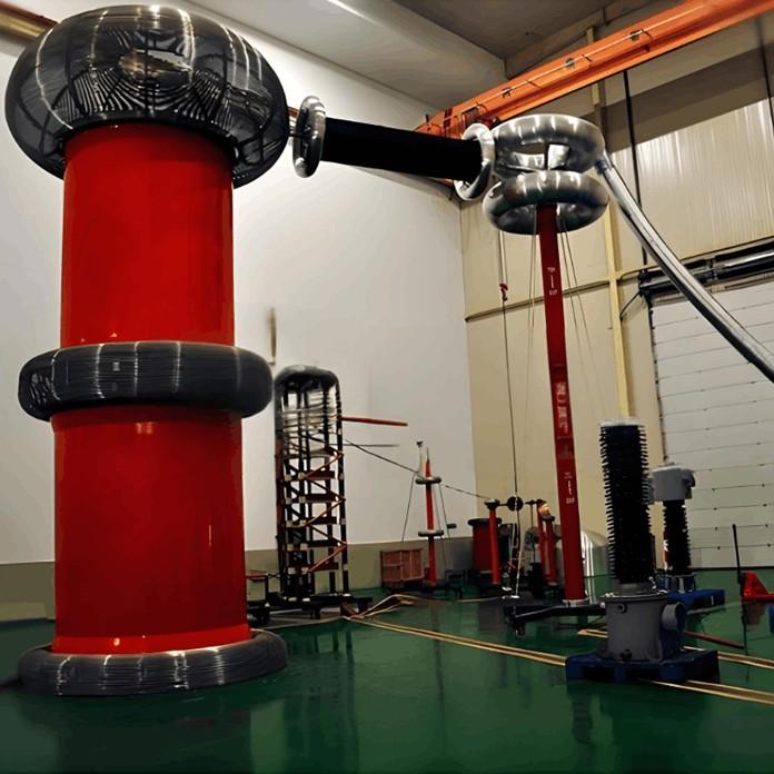
Key items (basic error, stability) reflect transformers&rsquo; measurement traits. Verification wiring is vital but cumbersome&mdash;different wires/terminals (fixed by nuts, matched to transformers, as in Figure 1) take much time, reducing efficiency.

2. Improvement of Verification Wiring

Traditional primary wires have drawbacks: verifying transformers with different ratios requires frequent primary wire replacements (to ensure accuracy), which is cumbersome and reduces efficiency. For example, testing the LDF1 - 0.66 low - voltage anti - theft current transformer (small aperture) causes issues as the primary wire can&rsquo;t pass through the core.

Key inefficiencies: 1) Many transformer types/ratios, varying primary core diameters. 2) Diverse primary rated currents/core sizes demand soft wires with different cross - sections and terminals. 3) Nut - screwed terminals add complexity.

Soft wires require matching terminals, causing messy wiring. Thus, copper rods replace soft wires&mdash;they offer good conductivity, sufficient strength, and simplify connections. Using workbench clamps and a rocker for fixation streamlines primary wiring, cutting time and boosting efficiency.

3. Comparative Analysis of Verification Data

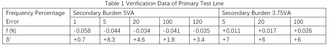
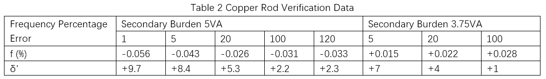
To verify the effectiveness of the copper rod wiring verification method, the conventional primary test line and copper rod wiring are respectively used to verify the same current transformer (model: LMZ1 - 0.5, transformation ratio: 150/5, class: 0.2S, rated burden: 5VA, factory number: 200000203). The key error data such as ratio difference and angle difference are shown in Tables 1 and 2.

By comparing the error data in Tables 1 and 2, it can be seen that the errors of both verification methods meet the requirements of the verification regulations, and the error curves are good. The wiring method does not affect the verification error data or the verification conclusion. Through sufficient and repeated tests, the effectiveness of the copper rod verification wiring method is verified.

4. Conclusion

This paper proposes a fast verification wiring method for low - voltage current transformers. A copper rod is used to replace the primary test line, making the wiring simple and convenient. The error data of the two wiring verification methods are compared and analyzed. Through repeated tests, the error curves are good and do not affect the verification data. This method improves work efficiency and avoids difficulties in verification.

Give a tip and encourage the author!
Recommended
A Guide to the Latest Transformer Testing Technologies
Transformers come in many types, primarily oil-immersed and dry-type. Their fault manifestations are diverse, but most failures are concentrated in the windings, core, connecting components, and oil contamination. For example, winding insulation damage, open circuits, short circuits, and inter-turn short circuits at connection points. Common external symptoms of transformer faults include severe overheating, excessive temperature rise, abnormal noise, and three-phase imbalance.Routine transforme
Oliver Watts
10/20/2025
Inspection of transformers can be performed without any detection tools.
Transformers are electrical devices that change voltage and current based on the principle of electromagnetic induction. In power transmission and distribution systems, transformers are essential for stepping up or stepping down voltages to reduce energy losses during transmission. For example, industrial facilities typically receive power at 10 kV, which is then stepped down to low voltage via transformers for on-site use. Today, let’s learn about several common transformer inspection methods.1
Oliver Watts
10/20/2025
Vacuum Circuit Breakers for Capacitor Bank Switching
Reactive Power Compensation and Capacitor Switching in Power SystemsReactive power compensation is an effective means to increase system operating voltage, reduce network losses, and improve system stability.Conventional Loads in Power Systems (Impedance Types): Resistance Inductive reactance Capacitive reactanceInrush Current During Capacitor EnergizationIn power system operation, capacitors are switched in to improve power factor. At the moment of closing, a large inrush current is generated.
Oliver Watts
10/18/2025
Vacuum Circuit Breaker Withstand Voltage Test Guide
Insulation Withstand Voltage Test Standards for Vacuum Circuit BreakersThe main purpose of the insulation withstand voltage test for vacuum circuit breakers is to verify whether the insulation performance of the equipment under high voltage is qualified, and to prevent breakdown or flashover accidents during operation. The test process must be strictly carried out in accordance with power industry standards to ensure equipment safety and power supply reliability.Test ObjectsThe test objects incl
Garca
10/18/2025
Send inquiry
Download
Get the IEE Business Application
Use the IEE-Business app to find equipment, obtain solutions, connect with experts, and participate in industry collaboration anytime, anywhere—fully supporting the development of your power projects and business.