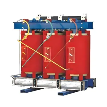
Causes of Winding Cracking in Epoxy Resin Cast Dry-Type Transformers and the Influence Mechanism of Thermal Cycling

Learn why epoxy cast dry-type transformer windings crack: thermal cycling effects, root causes, and how to prevent insulation failure.

Vziman
Field: Manufacturing
10Year<
China
Add us on Google
Epoxy resin cast dry-type transformers are widely used in power systems for their high reliability and maintenance-free operation. However, winding cracking remains a critical issue compromising their safe operation. Winding cracking not only increases partial discharge and distorts insulation monitoring data but can also lead to short-circuit faults and equipment scrapping in severe cases. To fundamentally resolve this problem, it is essential to thoroughly analyze the multidimensional triggering factors and clarify the key role of thermal cycling in the cracking process.

1. Multidimensional Triggering Factors of Winding Cracking

Winding cracking is not the result of a single failure but rather the interplay of multiple factors including materials, processes, structural design, and operating environment.

1.1 Evolution of Insulation Structure and Mismatch of Material Properties

Parameter Thick Insulation (Traditional) Thin Insulation (Modern)
Resin layer thickness 6–15 mm 1.5–2 mm
Reinforcement None Glass fiber
CTE mismatch stress High — significant shear stress at resin-conductor interface Low — elastic thin layer expands/contracts with winding
Cracking risk High Low (but filler quality remains critical)
 Early dry-type transformers used thick insulation, where the CTE mismatch between resin and conductor generated substantial interfacial shear stress under temperature variation, leading to cracking. Modern thin insulation, reinforced with glass fiber, flexes with the winding to alleviate thermal stress. However, insufficient resin toughness or poorly selected fillers (e.g., low-purity, overly coarse, or sharply shaped particles) can still create micro-defects that fracture the resin matrix under stress.

1.2 Improper Control of Casting and Curing Processes

During casting, if high-standard vacuum casting is not adopted or degassing is insufficient, air bubbles are likely to remain inside the resin. During the curing stage, if the heating, holding, and cooling profiles are improperly controlled, the resin cannot cure slowly and uniformly, resulting in excessive internal residual stress that creates inherent defects predisposing the material to later cracking.

1.3 Mechanical Stress and Electromagnetic Force Impact

During operation, transformers are subjected to external mechanical vibration as well as enormous electromagnetic forces during short-circuit events. If the coil winding is not tight or the support and fixing methods are inadequate, repeated electromagnetic forces and vibration can cause coil deformation, insulation layer damage, and even cracking.

1.4 Harsh Operating Environment

Prolonged exposure to high temperatures accelerates thermal aging and thermal decomposition of the resin, reducing its mechanical strength. In hot and humid environments, moisture ingress causes ester hydrolysis in the resin, forming micro-pores on the surface. Additionally, corrosive gases in environments such as chemical plants (e.g., sulfur dioxide, chlorine) can attack the insulation material and degrade its molecular structure.

2. Influence Mechanism of Thermal Cycling on the Resin Insulation Layer

Among the triggers described above, thermal cycling (temperature cycling) is the core physical mechanism that runs throughout the equipment's entire life cycle, acting as a "catalyst" that accelerates crack propagation. Research indicates that "thermo-mechanical fatigue" caused by thermal cycling is far more likely to induce micro-cracks in the insulation layer than continuous high-temperature exposure. Its impact on the resin insulation layer is primarily reflected in the following four aspects.

Mechanism Core Process Consequence
Alternating thermal stress accumulation CTE mismatch generates cyclic tensile and shear stresses at interfaces Interfacial bond weakening → micro-crack initiation → through-cracking
Microstructure deterioration Cross-linked network degrades, free volume increases Micro-voids and cracks on fracture surfaces; reduced AC breakdown strength
Tg critical effect Material transitions from glassy to highly elastic state near Tg Sharp CTE rise, modulus change, deformation resistance drop → interfacial debonding
PD vicious cycle Micro-air gaps form from cracking, field intensification triggers PD PD erosion further degrades resin → crack growth → eventual breakdown

2.1 Accumulation and Fatigue of Alternating Thermal Stress

Due to the CTE mismatch between the resin and the conductor, and between the resin and the glass fiber reinforcement, thermal cycling generates alternating tensile and shear stresses at the material interfaces. As the number of cycles increases, these stresses weaken the interfacial bonding strength, micro-cracks initiate and gradually propagate, ultimately developing into through-cracking.

2.2 Deterioration of Material Microstructure

Under the alternating temperature stress of thermal cycling, the cross-linked network of epoxy resin gradually degrades, and the free volume within the material increases. At the microscopic level, this manifests as voids and micro-cracks on fracture surfaces; at the macroscopic level, it appears as a decrease in the AC breakdown strength of the insulating material.

2.3 Critical Effect of Glass Transition Temperature (Tg)

When the operating temperature approaches or exceeds the glass transition temperature (Tg) of the epoxy resin, the coefficient of thermal expansion rises sharply and the modulus undergoes significant change. At this point, the material transitions from a rigid glassy state to a highly elastic state, its deformation resistance drops dramatically, and the internal stress concentration caused by thermal cycling more readily leads to interfacial debonding and cracking.

2.4 Vicious Cycle Triggering Partial Discharge (PD)

Cracking caused by thermal cycling creates micro-air gaps within the insulation layer. Since the dielectric constant of resin is far higher than that of air, under AC voltage the electric field strength in the air gap is distributed inversely proportional to the dielectric constant, resulting in extremely high field strength within the gap. This readily triggers partial discharge. The high-energy particles generated by PD further erode and degrade the epoxy resin, forming a vicious cycle of "cracking → PD → electrical erosion → aggravated cracking" that ultimately leads to insulation breakdown.

3. Summary and Systematic Defense Strategy

In summary, winding cracking in epoxy resin cast dry-type transformers is essentially a material fatigue and structural failure problem caused by multi-factor coupling. To fundamentally resolve this issue, a systematic defense strategy must be established across both manufacturing and operational phases.

Phase Focus Area Key Measures
Manufacturing Material formulation High-toughness resin, high-purity fillers
Manufacturing Process control Strict vacuum casting, programmed temperature curing
Operation Thermal management Ensure adequate heat dissipation, avoid extreme temperature shocks
Operation Load management Control load cycles to minimize thermal stress accumulation
 

Only by combining the enhancement of intrinsic material properties with life-cycle operation and maintenance management can the erosive effects of thermal cycling be effectively resisted, ensuring the long-term safe and stable operation of dry-type transformers.

Edited From:Leon
Give a tip and encourage the author!

Comments

Share your question or perspective
WhatsApp
Send inquiry
+86
Click to upload file
Download
Get the IEE Business Application
Use the IEE-Business app to find equipment, obtain solutions, connect with experts, and participate in industry collaboration anytime, anywhere—fully supporting the development of your power projects and business.
Login
or continue with
New here?
Register