What is a Coil Span Factor?

05/27/2025

Coil Span Factor (Pitch Factor) Definition and Characteristics
Definition of Pitch Factor (Kₙ)
The coil span factor (also known as the chording factor) Kₙ is defined as the ratio of the induced voltage in a short-pitched coil to that in a full-pitched coil. The distance between the two sides of a coil is termed the coil span, which is characterized by its electrical angle to indicate the degree of short-pitching.
Physical Meaning of Pole Pitch
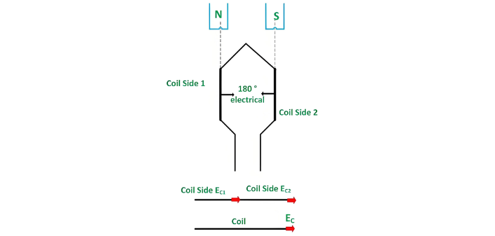
The angular distance between the central lines of adjacent poles is called the pole pitch, which always equals 180 electrical degrees regardless of the number of poles in the machine. A coil with a span of 180 electrical degrees is referred to as a full-pitched coil, as illustrated in the figure below:

Short-Pitched Coil Characteristics
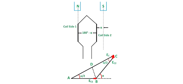
A coil with a span less than 180 electrical degrees is termed a short-pitched coil (or fractional-pitch coil), also known as a chorded coil. The short-pitch coil configuration is illustrated in the figure below:
Chorded Winding and Coil Span Calculation
A stator winding employing fractional-pitch coils is referred to as a chorded winding. If the coil span is reduced by an electrical angle α, the effective span becomes (180 – α) electrical degrees.
For a full-pitch coil, the distance between the two coil sides precisely equals the 180° electrical pole pitch, ensuring that voltages induced in each coil side are in phase. Let EC1 and EC2 denote the voltages generated in the coil sides, with EC as the resultant coil voltage. The relationship is expressed by the equation:
Since EC1 and EC2 are in phase, the resultant coil voltage EC equals the arithmetic sum of the two voltages.
Thus,
Phasor Analysis of Short-Pitched Coils
When the coil span of a single coil is less than the 180° electrical pole pitch, the voltages induced in each coil side EC1 and EC2 exhibit a phase difference. The resultant coil voltage EC is the phasor sum of EC1 and EC2.
If the coil span is reduced by an electrical angle α, the effective span becomes (180 – α) degrees. Consequently, EC1 and EC2 will be out of phase by α degrees. As shown in the phasor diagram above, the phasor sum EC corresponds to the vector AC.
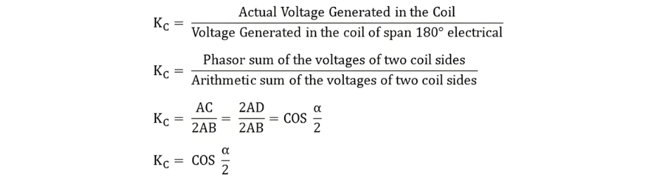
The coil span factor Kc is expressed as:

Pitch Factor (Kₙ) Characteristics and Advantages of Short-Pitched Windings
Relationship Between Pitch Factor and Coil Span

  • Full-pitched coil: When α = 0°, cos(α/2) = 1, hence Kₙ = 1.
  • Short-pitched coil: Kₙ < 1, indicating that short-pitching reduces the amplitude of induced voltage.

Technical Advantages of Short-Pitched Coils (Chorded Windings)

  • Material Cost Optimization:Shortens winding end-turn lengths, reducing conductor material usage and manufacturing costs.
  • Waveform Quality Enhancement:Suppresses harmonic distortion, making the induced EMF closer to a sine wave and improving power quality.

Zhejiang Vziman Electric Group Co., Ltd. is a high-tech enterprise specializing in R&D, manufacturing, and service of power electrical equipment. Committed to innovation, quality, and customer satisfaction, it supplies smart solutions for global power sectors, covering grid construction, new energy, and industrial distribution. Core Business • Switchgear (GIS, circuit breakers, Recloser, Load break switch) • Distribution equipment (transformers, RMU, smart terminals) • Power automation systems • Engineering services (installation, maintenance, consulting) Technical Strength • Provincial R&D center, multiple patents • Modern production, ISO/GB/IEC/CE/UL certified • High capacity, large-scale delivery support Market & Vision Serves State Grid, Southern Grid, and global projects (Asia, Africa, Europe, etc.). Aims to lead in smart grids and new energy, promoting sustainable energy development.

Difference Between Short Circuit & Overload
One of the main differences between a short circuit and an overload is that a short circuit occurs due to a fault between conductors (line-to-line) or between a conductor and earth (line-to-ground), whereas an overload refers to a situation where equipment draws more current than its rated capacity from the power supply.Other key differences between the two are explained in the comparison chart below.The term "overload" typically refers to a condition in a circuit or connected device. A circuit
08/28/2025
Difference Between Leading and Lagging Power Factor
Leading and lagging power factors are two key concepts related to the power factor in AC electrical systems. The main difference lies in the phase relationship between current and voltage: in a leading power factor, the current leads the voltage, whereas in a lagging power factor, the current lags behind the voltage. This behavior depends on the nature of the load in the circuit.What is Power Factor?Power factor is a crucial, dimensionless parameter in AC electrical systems, applicable to both s
08/26/2025
Difference Between Electromagnet and Permanent Magnet
Electromagnets vs. Permanent Magnets: Understanding the Key DifferencesElectromagnets and permanent magnets are the two primary types of materials that exhibit magnetic properties. While both generate magnetic fields, they differ fundamentally in how these fields are produced.An electromagnet generates a magnetic field only when an electric current flows through it. In contrast, a permanent magnet inherently produces its own persistent magnetic field once it has been magnetized, without requirin
08/26/2025
Interpretation of the “Five Mandatory Surveys” for On - site Investigation in the Operation and Maintenance Specialty
The power outage and work scopes must be clearly inspectedCollaborate with the site survey leader to confirm the equipment to be maintained and the work area involved. Consider requirements such as the use of special vehicles and large machinery, and safe distances from adjacent energized equipment. Verify on-site whether the proposed power outage scope is sufficient to meet the operational needs.On-site safety measures must be clearly inspectedCollaborate with the site survey leader to verify s
Vziman
08/14/2025
Inquiry
Download
IEE-Business is dedicated to serving the personnel in the global power industry.
Join IEE-Business, not only can you discover power equipment and power knowledge, but also canhnd like - minded friends!