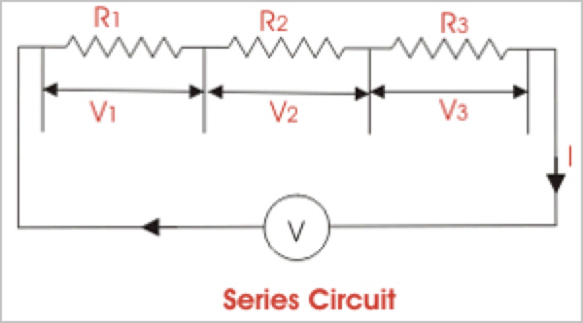
تعني المقاومة المتسلسلة ترتيب مقاومات فردية متصلة بشكل متتالي في الدائرة بحيث يتدفق التيار عبر كل مقاومة. في هذا التكوين، تكون المقاومة الكلية (R) للدائرة مساوية لمجموع المقاومات الفردية، والتي تُعرف أيضًا بالمقاومة المكافئة R.
لحساب المقاومة الكلية في دائرة متسلسلة، يتم جمع المقاومات الفردية لكل مقاومة معًا. الصيغة لحساب المقاومة المكافئة في الاتصال المتسلسل هي Rtotal = R1 + R2 + R3 + ...، حيث تمثل R1 و R2 و R3 وما إلى ذلك المقاومات الفردية لكل مقاومة في الدائرة.
تطبق قانون أوم على الدوائر المتسلسلة أيضًا، حيث يكون التيار عبر كل مقاومة هو نفسه، ولكن الجهد عبر كل مقاومة يتناسب مع مقاومتها. الجهد الكلي عبر التركيب المتسلسل للمقاومات يساوي مجموع الانخفاضات الجهد عبر كل مقاومة.
من المهم ملاحظة أن المقاومة الكلية في الدائرة المتسلسلة دائمًا أكبر من مقاومة أي مقاومة فردية في الدائرة بسبب التأثير التراكمي لكل مقاومة.
من ناحية أخرى، يؤدي ربط المقاومات بالتوازي إلى تكوين دائرة متوازية. يتم حساب المقاومة المكافئة للدائرة المتوازية بطريقة مختلفة عن الاتصال المتسلسل. بدلاً من جمع المقاومات الفردية، يتم جمع المعكوس لكل مقاومة، ثم يتم عكس القيمة الناتجة للحصول على المقاومة المكافئة.
المقاومة في التوصيل المتسلسل - المتوازي
عند وضع R-I-S، تضيف قيمها الأومية حسابيًا للوصول إلى المقاومة الكلية (أو الصافية).
يمكننا ربط سلسلة من المقاومات (تساوي مجموع المقاومات الفردية للدائرة المتوازية)، جميعها ذات قيم أومية متماثلة، في مجموعات متوازية من الشبكات المتسلسلة أو مجموعات متسلسلة من الشبكات المتوازية. عندما نقوم بأي من هذين الأمرين، نحصل على شبكة متسلسلة-متوازية يمكن أن تزيد بشكل كبير من طاقة التعامل الكلية للشبكة أكثر من طاقة التعامل لأي مقاومة متوازية واحدة.
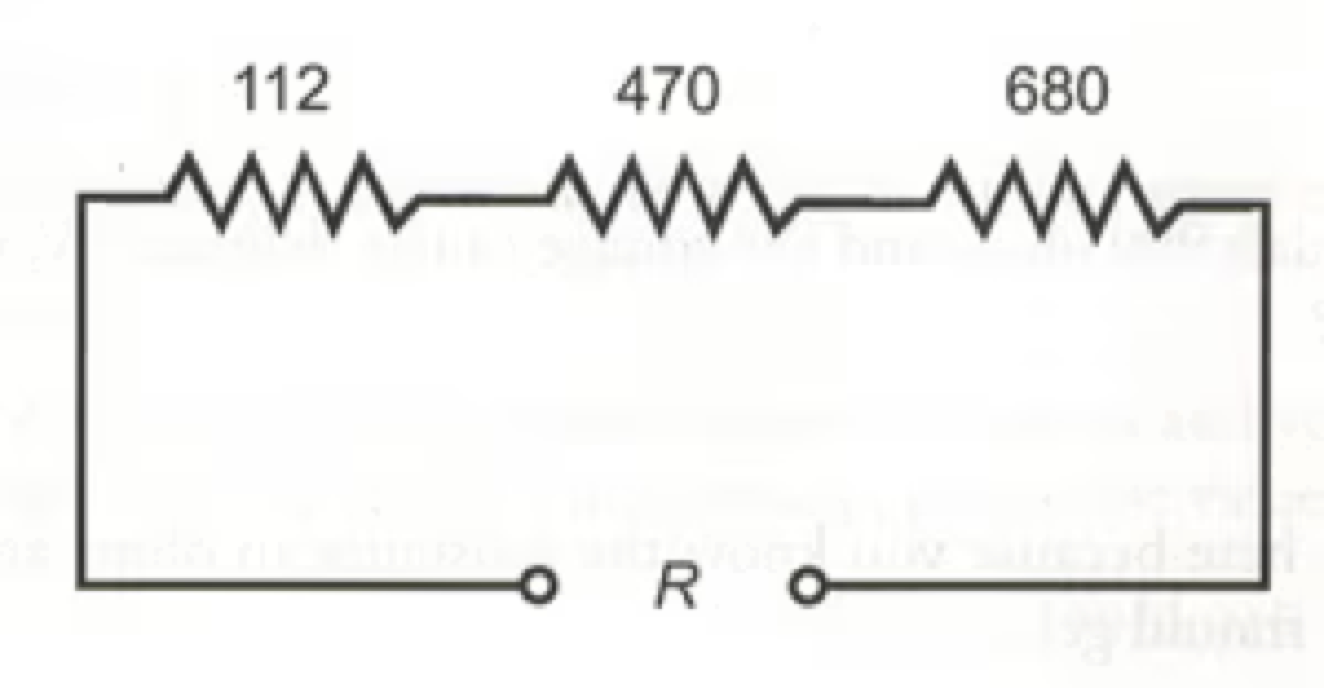
الشكل 4-14. ثلاثة مقاومات متسلسلة.
في بعض الأحيان، تكون المقاومة الكلية المكافئة الواحدة للدائرة المتسلسلة-المتوازية مساوية لقيمة أي مقاومة منها. يحدث هذا دائمًا إذا كانت الفروع المتوازية أو تركيبات المكونات المتوازية متماثلة ومرتبة في شبكة تسمى مصفوفة n-by-n (أو n x n). وهذا يعني أنه عندما يكون n عددًا صحيحًا، لدينا n مجموعة متسلسلة من n مقاومة متصلة بالتوازي، أو لدينا n مجموعة متوازية من n مقاومة متصلة بشكل متسلسل في الدائرة. تؤدي هاتان الترتيبتان إلى نفس النتيجة العملية للدوائر الكهربائية.
مزيج من مجموعات المقاومات المتسلسلة-المتوازية بترتيب n by n، جميعها ذات قيم أومية متماثلة وتصنيفات قوة متماثلة، سيكون لديه n2 مرة من قدرة التعامل عن أي مقاومة بمفردها. على سبيل المثال، يمكن لمصفوفة 3 x 3 من مقاومات 2 واط التعامل مع ما يصل إلى 32 x 2 = 9 x 2 = 18 واط. إذا كان لدينا مصفوفة 10 x 10 من مقاومات 1/2 واط، فيمكنها تبديد ما يصل إلى 102 x 1/2 = 50 واط. نضرب قدرة التعامل لكل مقاومة فردية في العدد الكلي للمقاومات في المصفوفة.
يعمل النظام المذكور أعلاه إذا، ولكن فقط إذا، كانت جميع المقاومات لها قيم أومية متماثلة وفقًا لقانون أوم وتصنيفات تبديد قوة متماثلة من حيث الانخفاضات الجهد الكلية عندما يكون مجموع الانخفاضات الجهد عبر كل مقاومة. إذا كانت المقاومات لها قيم تختلف حتى قليلًا عن بعضها البعض، فمن المحتمل أن يسحب أحد المكونات المزيد من التيار مما يمكنه تحمله وبالتالي سيحترق، بغض النظر عن مصدر الجهد. ثم ستتغير توزيعات التيار في الشبكة بشكل أكبر، مما يزيد من احتمالية فشل مقاومة ثانية، وأكثر.
إذا كنت تحتاج إلى مقاومة يمكنها التعامل مع 50 واط وأن اتصالًا متسلسلًا-متوازيًا معينًا للشبكة يمكنه التعامل مع 75 واط، فهذا جيد. ولكن你不应该期望使用仅能处理48瓦的网络来满足同样的应用。你应该允许一些额外的余量,比如比最小额定值多10%。如果你期望网络能够耗散50瓦,你应该构建它以处理55瓦或更多。你不必过度设计,但是如果你用现有的电阻器只能组合出能够处理500瓦的网络,而你只需要它处理50瓦,那么除非这是唯一方便的组合,否则你会浪费资源。
Statement: Respect the original, good articles worth sharing, if there is infringement please contact delete. Resistance in series refers to the arrangement of individual resistors end to end in a circuit so that the current flows through each resistor. In this configuration, the total resistance (R) of the circuit is equal to the sum of the individual resistances, also known as the equivalent R. To calculate the total R in a series circuit, the individual resistances of each resistor are added together. The formula to calculate the equivalent resistance in a series connection is Rtotal = R1 + R2 + R3 + ..., where R1, R2, R3, etc., represent the individual resistances of each resistor in the circuit. Ohm's law also applies to series circuits, where the current through each resistor is the same, but the voltage across each resistor is proportional to its R. The total voltage across the series combination of resistors equals the sum of the voltage drops across each resistor. It is important to note that the total R in a series circuit is always greater than the resistance of any individual resistor in the circuit due to the cumulative effect of each resistor's R. On the other hand, resistors connected in parallel result in a parallel circuit. The equivalent R of a parallel circuit is calculated differently from a series connection. Instead of adding the individual resistances, the reciprocal of each R is added, and the resulting value is inverted to obtain the equivalent resistance. R in Series - Parallel When you place R-I-S, their ohmic values add up arithmetically to reach the total (or net) R. We can connect a series of resistors (equal to the sum of the individual resistances of a parallel circuit), all having identical ohmic values, in parallel sets of series networks or series sets of parallel networks. When we do either of these things, we get a series-parallel network that can greatly increase the total power handling capacity of the network over the power-handling capacity of a single parallel resistor. Sometimes, the total single equivalent R of the combination circuit in a series parallel network equals the value of any one of the resistors. This always happens if the parallel branches or parallel combinations of the connection components are all identical and are arranged in a network called an n-by-n (or n x n) matrix. That means when n is a whole number, we have n series sets of n resistors connected in parallel, or else we have n parallel sets of n resistors connected in series in the circuit. These two arrangements yield the same practical result for electrical circuits. A combination of series parallel combinations array of n by n resistors, all having identical ohmic values and identical power ratings, will have n2 times the power-handling capability of any resistor by itself. For example, a 3 x 3 series-parallel matrix of 2 W resistors can handle up to 32 x 2 = 9 x 2 = 18 W. If we have a 10 x 10 array of 1/2 W resistors, then it can dissipate up to 102 x 1/2 = 50 W. We multiply the power-handling capacity of each individual resistor by the total number of resistors in the matrix. The above-described scheme works if, but only if, all of the resistors have identical ohmic values according to ohms law and identical power-dissipation ratings in terms of total voltage drops when the sum of the voltage drops across each resistor. If the resistors have values that differ even a little bit from one another, one of the components will likely draw more current than it can withstand so that it will burn out, no matter the voltage source. Then the current distribution in the network will change further, increasing the likelihood that a second resistor will fail, and maybe more. If you need a resistor that can handle 50 W and a certain series-parallel connection of the network will handle 75 W, that's fine. But you should not "push your luck" and expect to get away with using a network that will handle only 48 W in the same application. You should allow some extra tolerance, say 10 per cent over the minimum rating. If you expect the network to dissipate 50W, you should build it to handle 55 W or a bit more. You don't have to use "overkill," however. You'll waste resources if you cobble together a network that can handle 500W when you only expect it to cope with 50W—unless that's the only convenient combination you can make with available resistors. Statement: Respect the original, good articles worth sharing, if there is infringement please contact delete.
Fig. 4-14. Three resistors in series.