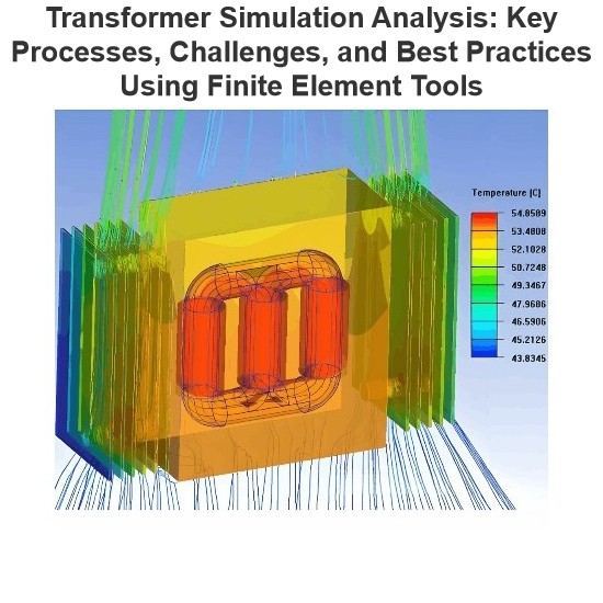
1 IntroductionWhether using any finite element analysis software (such as COMSOL, Infolytica, or Ansys) for transformer simulation analysis—whether focusing on electric field, magnetic field, flow field, mechanical field, or acoustic field—the basic process is roughly the same. A true understanding of the key points in each process is the foundation for the success of the simulation analysis and the reliability of the final results.2 Basic Simulation ProcessA scientific and c
07/29/2025
Consult
Tip
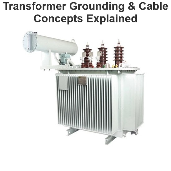
Sharing of Transformer Concepts and Terminology The zero-mode impedance of a load is infinite, and its line-mode impedance is also extremely large, approximately 100 times that of the line-mode impedance of the line. The capacitance to ground of a cable is 25-50 times that of an overhead line. The free oscillation frequency of transient capacitive current: 300-1500Hz for overhead lines and 1500-3000Hz for cables. Performance requirements for an external grounding transformer: Under normal power
07/28/2025
Consult
Tip
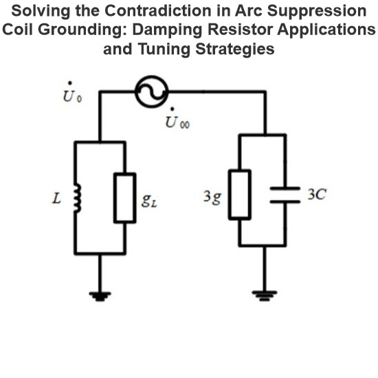
Contradiction PointsIn automatic tracking arc suppression coils, the adjustment precision is high, the residual current is small, and the operation is close to the resonance point.In an automatic tracking arc suppression coil grounding system, two factors must be considered: Under normal operating conditions, the long-term voltage displacement of the neutral point should not exceed 15% of the system's nominal phase voltage; In the case of a ground fault, the grounding residual current should b
07/28/2025
Consult
Tip
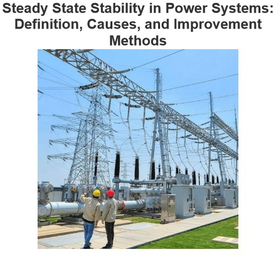
Definition of Steady State StabilitySteady state stability is defined as the capability of an electric power system to sustain its initial operating condition following a small disturbance, or to converge to a state closely approximating the initial condition when the disturbance persists. This concept holds critical significance in power system planning and design, the development of specialized automatic control devices, the commissioning of new system components, and the adjustment of operati
07/26/2025
Consult
Tip
Definition of Voltage StabilityVoltage stability in a power system is defined as the ability to maintain acceptable voltages at all buses under both normal operating conditions and after being subjected to a disturbance. In normal operation, the system’s voltages remain stable; however, when a fault or disturbance occurs, voltage instability may arise, leading to a progressive and uncontrollable voltage decline. Voltage stability is sometimes referred to as "load stability."Voltage instability c
07/26/2025
Consult
Tip
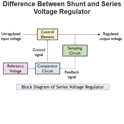
Linear voltage regulators are mainly classified into two types: shunt voltage regulators and series voltage regulators. The key difference between them lies in the connection of the control element: in a shunt voltage regulator, the control element is connected in parallel with the load; in contrast, in a series voltage regulator, the control element is connected in series with the load. These two types of voltage regulator circuits operate on different principles and thus have their own advanta
07/25/2025
Consult
Tip
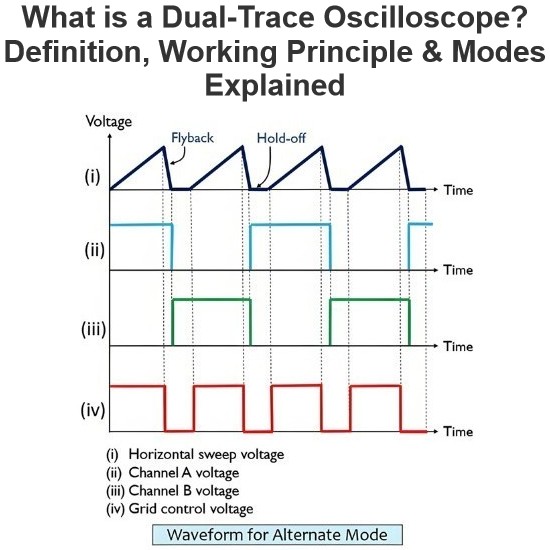
What is Dual Trace Oscilloscope?DefinitionA dual-trace oscilloscope uses a single electron beam to generate two separate traces, each deflected by an independent input source. To produce these two traces, it primarily employs two operating modes—alternate mode and chopped mode—controlled by a switch.Purpose of a Dual-Trace OscilloscopeWhen analyzing or studying multiple electronic circuits, comparing their voltage characteristics is often critical. While one could use multiple oscilloscopes for
07/25/2025
Consult
Tip

What is Cathode Ray Oscilloscope (CRO)?DefinitionA cathode ray oscilloscope (CRO) is an electrical instrument for measuring, analyzing and visualizing waveforms and other electronic/electrical phenomena. As a high - speed X - Y plotter, it shows an input signal against another signal or time. Capable of analyzing waveforms, transient phenomena and time - varying quantities across a wide frequency range (from very low to radio frequencies), it mainly operates on voltage. Other physical quantities
07/25/2025
Consult
Tip
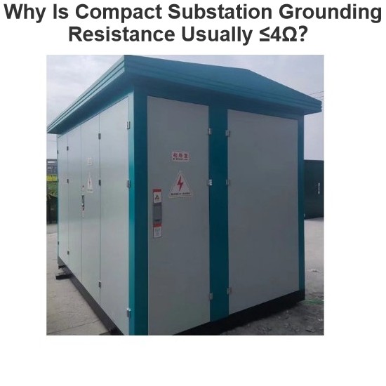
As a key power distribution equipment, the safe operation of a compact substation relies on reliable grounding measures. People often wonder: Why is the grounding resistance of a compact substation generally required to be no more than 4Ω? Behind this value, there are rigorous technical bases and application scenario restrictions. In fact, the requirement of ≤4Ω is not mandatory in all cases. It mainly applies to scenarios where the high - voltage system adopts "ungrou
07/23/2025
Consult
Tip
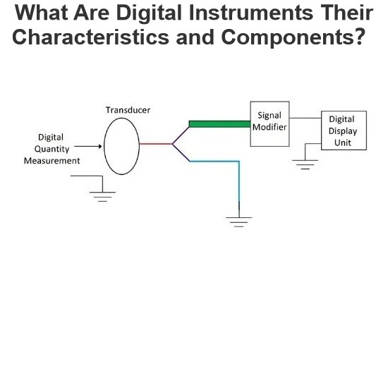
Definition of Digital InstrumentsA digital instrument is a device that displays the value of a measured quantity in the form of digital numbers. It operates on the principle of quantization—the process of converting a continuous input signal into a countable output signal.Digital instruments have a relatively complex structure and are generally more expensive. However, they consume significantly less power compared to analog instruments. Examples include digital multimeters, digital vo
07/23/2025
Consult
Tip


