1 Introduction
Whether using any finite element analysis software (such as COMSOL, Infolytica, or Ansys) for transformer simulation analysis—whether focusing on electric field, magnetic field, flow field, mechanical field, or acoustic field—the basic process is roughly the same. A true understanding of the key points in each process is the foundation for the success of the simulation analysis and the reliability of the final results.
2 Basic Simulation Process
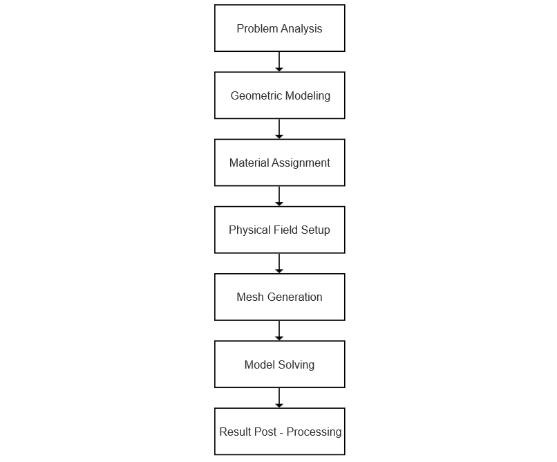
A scientific and complete transformer simulation process includes seven major steps:
3 Understanding of Difficulty
A transformer is a static electrical device, and from this perspective, its related simulation work is relatively simple, as the presence of rotating components would significantly increase the difficulty of most simulations. Unfortunately, however, a transformer is also a nonlinear, time-varying electromechanical device with strong coupling of multiple physical fields, which often makes transformer simulation much more difficult and even unsolvable.
For example, simulations of transformer temperature fields based on fluid analysis often fail to yield accurate and reliable results. One reason is that the basic theory of fluid dynamics itself is highly complex and has not yet formed a unified and stable theory. On the other hand, temperature field simulation of transformers requires bidirectional strong coupling of three fields: "magnetic field—heat transfer field—fluid field." For such a large transformer model, solving a single flow field is already challenging,let alone the ultra - strong coupling of three fields
To achieve breakthroughs in key areas of transformer simulation, simulation engineers must, on one hand, have a deep understanding of transformer-related theories, design, manufacturing, and testing knowledge, and on the other hand, be highly proficient in operating simulation software and understand the intrinsic nature of its operation.
4 Key Points of the Process
4.1 Problem Analysis
Before geometric modeling, a preliminary analysis of the simulation problem is required to establish an appropriate geometric model and select the correct physical field. For example, is the simulation problem focused on a single physical field or strongly coupled physical fields?
4.2 Geometric Modeling
The completeness of geometric modeling determines the efficiency and progress of the simulation. In most cases, a simplified geometric model needs to be established. However, if the geometric model is overly simplified, the simulation results will be inaccurate and unable to guide the design work. Clearly, determining how to simplify the geometric model requires a profound understanding of the problem being solved. For instance, is a 2D geometric model sufficient? Is it necessary to build a 3D geometric model? Even when building a 3D model, which details can be omitted and which must be retained?
4.3 Material Assignment
A material may have dozens of physical parameters, but only a few are often required for solving a specific problem.
When assigning specific material parameters, their values must be accurate; otherwise, unacceptable deviations may be introduced into the simulation results.
Some material property parameters vary with other parameters. For example, in transformer fluid-thermal simulations, the density, specific heat capacity, and thermal conductivity of transformer oil change with temperature, and these relationships must be described using relatively accurate functions.
4.4 Physical Field Setup
For the selected physical field, it is necessary to define essential solving conditions, such as the physical equations governing the problem, expressions of excitations, initial conditions, boundary conditions, and constraint conditions.
4.5 Mesh Generation
Mesh generation is arguably the core step after geometric modeling. Theoretically, finer meshes yield more accurate results. However, excessively fine meshes are impractical, as they significantly increase solving time.
The basic principle of mesh generation is to combine coarse and fine meshes appropriately: refine where necessary and coarsen where possible.
Manual mesh generation is highly challenging and requires simulation engineers to have a deep understanding of the problem being solved.
Fortunately, some software offers physics-based automatic mesh generation functions, which often simplify the mesh generation process. For example, COMSOL’s automatic mesh generation function for electric field simulation modules is extremely powerful, enabling rapid meshing of large transformer main insulation models at a speed nearly 40 times faster than other software.
Unfortunately, the software’s built-in automatic mesh generation functions are insufficient for solving certain problems, as general-purpose software cannot identify areas requiring mesh refinement—such as in flow field simulations.
4.6 Model Solving
The essence of simulation solving is solving large discrete equation systems. This requires simulation engineers to have knowledge of relevant mathematics, such as matrix theory and Newton iteration methods.
Some software solvers are automatically configured based on the problem, requiring no additional intervention from the engineer. However, like mesh generation, this is not universally applicable. Solving advanced and complex problems requires engineers to configure settings individually to ensure rapid convergence and accurate results.
4.7 Result Post-Processing
To intuitively present simulation results, the obtained data needs appropriate post-processing, such as generating electric field contour plots, temperature field contour plots, or flow field contour plots.
In addition, some post-processing steps require engineers to apply professional knowledge. For example, most electric field simulation software can only intuitively display the magnitude of electric field intensity at each point, but determining the feasibility of insulation margin requires statistical analysis of this data to generate insulation margin curves based on cumulative field strength.