• Product
  • Suppliers
  • Manufacturers
  • Solutions
  • Free tools
  • Knowledges
  • Experts
  • Communities
Search


What is Cathode Ray Oscilloscope (CRO)?

Edwiin
Edwiin
Field: Power switch
China

What is Cathode Ray Oscilloscope (CRO)?

Definition

A cathode ray oscilloscope (CRO) is an electrical instrument for measuring, analyzing and visualizing waveforms and other electronic/electrical phenomena. As a high - speed X - Y plotter, it shows an input signal against another signal or time. Capable of analyzing waveforms, transient phenomena and time - varying quantities across a wide frequency range (from very low to radio frequencies), it mainly operates on voltage. Other physical quantities (current, strain, etc.) can be converted to voltage via transducers for display.

Key Operation

A luminous spot (from an electron beam hitting a fluorescent screen) moves on the display per input voltages. A standard CRO uses an internal horizontal ramp voltage ("time base") for left - to - right horizontal movement, with vertical movement controlled by the voltage under test, enabling stationary viewing of fast - varying signals.

Construction

Main components:

  • Cathode Ray Tube (CRT):A vacuum tube converting electrical to visual signals, with an electron gun and electrostatic deflection plates (vertical/horizontal). The gun produces a focused, high - speed electron beam; plates move the beam independently for screen positioning.

  • Electronic Gun Assembly:Emits and shapes the electron beam, including heater, cathode (barium/strontium - coated for electron emission), control grid (regulates beam intensity via negative potential), and anodes (for acceleration at ~1500V). Focusing uses electrostatic methods (standard in CROs).

  • Deflecting Plates:Two pairs: “Y plates” (vertical) and “X plates” (horizontal) control beam movement.

  • Fluorescent Screen:CRT faceplate (flat for small, curved for large screens) coated with phosphor. Electrons striking it cause fluorescence (light emission).

  • Glass Envelope:Highly evacuated, cone - shaped. Inner surface has aquadag (conductive coating connected to the accelerating anode) to aid electron focusing.

Working Principle

Electrons from the cathode pass through the control grid (negative potential adjusts intensity). Accelerated by anodes, focused, and deflected by plates per input voltages, they hit the screen, creating a visible spot to trace waveforms.

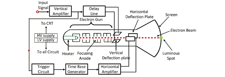
After passing through the control grid, the electron beam travels through the focusing and accelerating anodes. The accelerating anodes, at a high positive potential, converge the beam to a point on the screen.

Emerging from the accelerating anode, the beam then comes under the influence of the deflecting plates. With zero potential on the deflecting plates, the beam forms a spot at the center of the screen. Applying a voltage to the vertical deflecting plates deflects the electron beam upward; applying a voltage to the horizontal deflecting plates deflects the light spot horizontally.

Give a tip and encourage the author!
Recommended
 Causes and Preventive Measures of Fire and Explosion in Oil Circuit Breakers
Causes and Preventive Measures of Fire and Explosion in Oil Circuit Breakers
Causes of Fire and Explosion in Oil Circuit Breakers When the oil level in an oil circuit breaker is too low, the oil layer covering the contacts becomes too thin. Under the effect of the electric arc, the oil decomposes and releases flammable gases. These gases accumulate in the space beneath the top cover, mixing with air to form an explosive mixture, which can ignite or explode under high temperature. If the oil level inside the tank is too high, the released gases have limited space to expan
Felix Spark
11/06/2025
THD Measurement Error Standards for Power Systems
Error Tolerance of Total Harmonic Distortion (THD): A Comprehensive Analysis Based on Application Scenarios, Equipment Accuracy, and Industry StandardsThe acceptable error range for Total Harmonic Distortion (THD) must be evaluated based on specific application contexts, measurement equipment accuracy, and applicable industry standards. Below is a detailed analysis of key performance indicators in power systems, industrial equipment, and general measurement applications.1. Harmonic Error Standar
Edwiin
11/03/2025
How Vacuum Tech Replaces SF6 in Modern Ring Main Units
Ring main units (RMUs) are used in secondary power distribution, directly connecting to end-users such as residential communities, construction sites, commercial buildings, highways, etc.In a residential substation, the RMU introduces 12 kV medium voltage, which is then stepped down to 380 V low voltage through transformers. The low-voltage switchgear distributes electrical energy to various user units. For a 1250 kVA distribution transformer in a residential community, the medium-voltage ring m
James
11/03/2025
Why Monitoring Accuracy Matters in Power Quality Systems
The Critical Role of Monitoring Accuracy in Power Quality Online DevicesThe measurement accuracy of online power quality monitoring devices is the core of the power system’s “perception capability,” directly determining the safety, economy, stability, and reliability of power supply to users. Inadequate accuracy leads to misjudgment, incorrect control, and flawed decision-making—potentially causing equipment damage, economic losses, or even grid failures. Conversely, high accuracy enables precis
Oliver Watts
10/30/2025
Send inquiry
Download
Get the IEE Business Application
Use the IEE-Business app to find equipment, obtain solutions, connect with experts, and participate in industry collaboration anytime, anywhere—fully supporting the development of your power projects and business.