What is Static Voltage Regulator?

05/21/2025

Types of Static Voltage Regulator

The static voltage regulator is superior to electromechanical regulators in respect of the accuracy of control, response, reliability and maintenance. The static voltage regulator is mainly classified into two types. They are;

  • Servo Type Voltage Regulator
  • Magnetic Amplifier Regulator

The types of static voltage regulator are described below in details;

Servo Type Voltage Regulator

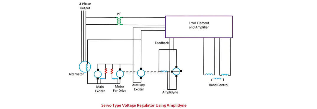
The main feature of the servo type voltage regulator is the use of the amplidyne. The amplidyne is a type of an electromechanical amplifier which amplifies the signal. The system contains the main exciter driven from the alternator shaft and an auxiliary exciter whose field winding is controlled by the amplidyne.

Both the auxiliary exciter and amplidyne are driven by a DC motor coupled to both the machines. The main exciter has a saturated magnetic circuit and hence has a rough output voltage. The armature of main and auxiliary exciter are connected in series, and this series combination excites the field winding of the alternator.

Working  of Servo type Voltage Regulator

The potential transformer provides a signal which is proportional to the output signal of the alternator.The output terminals of the alternator are connected to the electronic amplifier. When the deviation occurs in the output voltage of the alternator, then the electronic amplifier sends the voltage to the amplidyne. The amplidyne output feeds the voltage to the amplidyne control field and hence alters the auxiliary exciter field. Thus, the auxiliary and the main exciter in series adjust the excitation current of the alternator.

Magnetic Amplifier Regulator
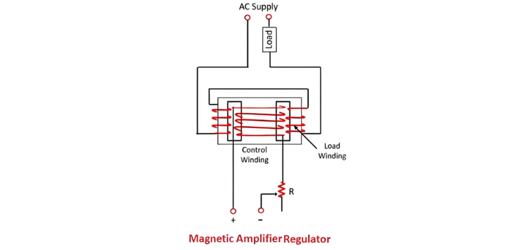
The key element of magnetic amplifiers is a steel - cored coil that has an additional winding energized by direct current (DC). This additional winding serves the purpose of controlling a relatively high - power alternating current (AC) using a low - power DC. The steel core of the regulator is equipped with two identical AC windings, which are also referred to as load windings. These AC windings can be connected either in series or in parallel, and in both cases, they are connected in series with a load.
The series winding configuration is employed when short - time response and high voltage are required, while the parallel winding setup is utilized for applications that demand a slow response. The control winding is powered by direct current (DC). When there is no current flowing through the load winding, the AC winding presents the highest impedance and inductance to an AC source. As a result, the alternating current supplied to the load is restricted by the high inductive reactance, leading to a low load voltage.
When a DC voltage is applied, the DC magnetic flux traverses the core, driving it towards magnetic saturation. This process reduces the inductance and impedance of the AC windings. As the DC current through the control winding increases, the alternating current flowing through the field winding also rises. Consequently, a minor adjustment in the magnitude of the load current can result in a significant variation in the load voltage.

The Electricity Encyclopedia is dedicated to accelerating the dissemination and application of electricity knowledge and adding impetus to the development and innovation of the electricity industry.

What is the difference between a dielectric and an insulator?
Dielectrics and insulators are distinguished primarily by their applications. One of the main differences is that a dielectric can store electrical energy by becoming polarized in an electric field, whereas an insulator resists the flow of electrons to prevent current conduction. Other key differences between them are outlined in the comparison chart below.Definition of DielectricA dielectric material is a type of insulator that contains few or no free electrons. When subjected to an electric fi
08/30/2025
Difference Between Transducer & Inverse Transducer
One of the primary differences between a transducer and an inverse transducer is that a transducer converts a non-electrical quantity into an electrical quantity, whereas an inverse transducer converts an electrical quantity into a non-electrical quantity. Other differences between the two are summarized in the comparison chart below.The control of physical quantities such as flow, rate, position, speed, temperature, and pressure depends on the accurate measurement of these quantities. In simple
08/28/2025
Transformer Connection Sections
Transformer Connection DesignationsThe transformer connection designation indicates the winding connection method and the phase relationship between the line voltages of the primary and secondary windings. It consists of two parts: letters and a number. The letters on the left denote the connection configurations of the high-voltage and low-voltage windings, while the number on the right is an integer from 0 to 11.This number represents the phase shift of the low-voltage winding's line voltage r
08/15/2025
Automatic Reclosing Scheme in Transmission Systems
Automatic Reclosing Scheme for Transmission SystemsThe automatic reclosing system is a series-connected network designed to reduce operating costs and enhance network reliability. Extra-high voltage (EHV) transmission lines are used to transmit large amounts of power, on the order of thousands of megawatts (MW), and therefore should not be interrupted at all costs. Although faults on these overhead lines are common, the power transmitted through them should not be interrupted for long periods du
08/07/2025
Inquiry
Download
IEE-Business is dedicated to serving the personnel in the global power industry.
Join IEE-Business, not only can you discover power equipment and power knowledge, but also canhnd like - minded friends!