• Product
  • Suppliers
  • Manufacturers
  • Solutions
  • Free tools
  • Knowledges
  • Experts
  • Communities
Search


RNB5-9 PC Transparent Cover Distribution Box

  • RNB5-9 PC Transparent Cover Distribution Box
  • RNB5-9 PC Transparent Cover Distribution Box
  • RNB5-9 PC Transparent Cover Distribution Box
  • RNB5-9 PC Transparent Cover Distribution Box

Key attributes

Brand Switchgear parts
Model NO. RNB5-9 PC Transparent Cover Distribution Box
Mounting type Concealed installation
number of circuit 9
Series RNB5

Product descriptions from the supplier

Description

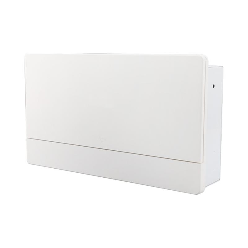
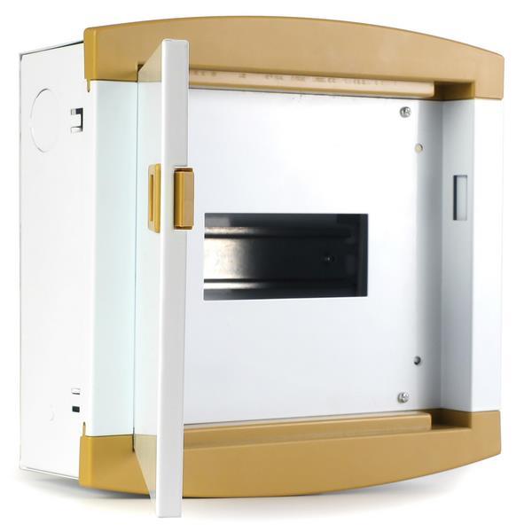
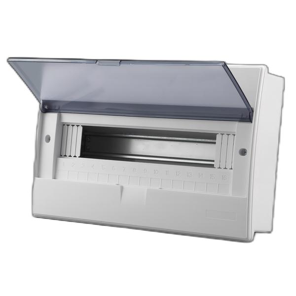
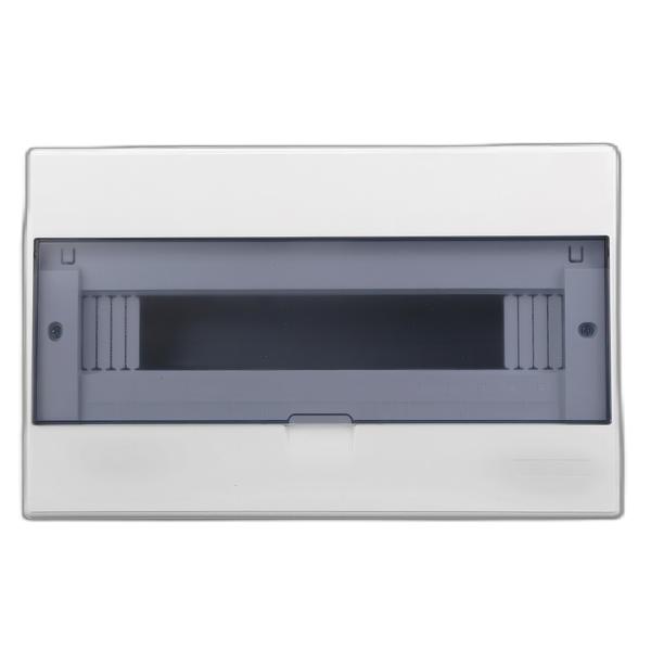
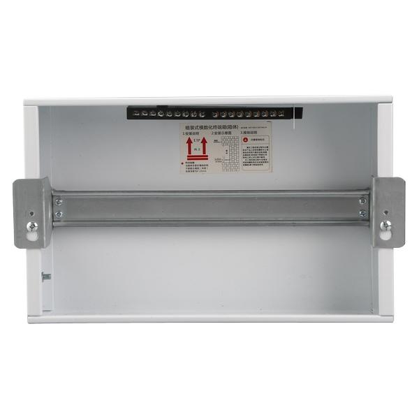
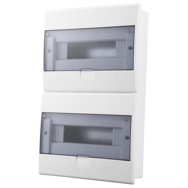
The RNB5 series terminal distribution box is made of fire-resistant and flame-retardant ABS, with a transparent cover made of PC and a bottom box made of cold-rolled steel plate. The panel is processed by technology, and the imitation leather pattern highlights the product grade and quality of life.

RNB5 series metal box residential distribution box application scenarios:
1. Distribution system: Electrical installation, supporting facilities, and renovation and decoration of building electrical distribution systems.
2. Installation method: The metal box body is matched with a plastic cover, which is particularly suitable for concealed installation of distribution boxes in construction and decoration projects.
3. Exterior Design: Fashionable exterior design is suitable for places that showcase modern lifestyle such as residences, hotels, and office buildings.
4. Compliant with standards: The product has been obtained first and meets the standards of GB17466.1 and GB17466.24.

Concealed size

Item

Row number

Specification

Overall dimensions (mm)

Bottom box size (mm)

RNB5-9

1

9

 240x200x95

217x180x75

RNB5-12

1

12

295x230x95

270x210x75

RNB5-16

1

16

366x230x95

340x210x75

RNB5-20

1

20

438x230x95

412x210x75

RNB5-24

2

24

295x395x95

268x375x75

RNB5-32

2

32

366x395x95

340x375x75

RNB5-40

2

40

438x395x95

412x375x75

RNB5-48

3

48

366x690x95

340x670x75

RNB5-60

3

60

438x690x95

412x670x75

Open installation size

Item

Row number

Specification

Overall dimensions (mm)

Bottom box size (mm)

RNB5-9M

1

9

240x200x95

240x200x75

RNB5-12M

1

12

295x230x95

295x230x75

RNB5-16M

1

16

366x230x95

366x230x75

RNB5-20M

1

20

438x230x95

438x230x75

RNB5-24M

2

24

295x395x95

295x395x75

RNB5-32M

2

32

366x395x95

366x395x75

RNB5-40M

2

40

438x395x95

438x395x75

RNB5-48M

3

48

366x690x95

366x690x75

RNB5-60M

3

60

438x690x95

438x690x75

Know your supplier
Online store
On-time delivery rate
Response time
100.0%
≤4h
Company overview
Workplace: 1000m² Total staff: Highest Annual Export(usD): 300000000
Workplace: 1000m²
Total staff:
Highest Annual Export(usD): 300000000
Services
Business Type: Sales
Main Categories: Low Voltage Electrical Apparatus/Instrument meters/Production equipment/Tester/High Voltage Electrical Apparatus/Electrical fittings/Equipment Parts
Whole life care manager
Whole-life care management services for equipment procurement, use, maintenance, and after-sales, ensuring safe operation of electrical equipment, continuous control, and worry-free electricity consumption.
The equipment supplier has passed platform qualification certification and technical evaluation, ensuring compliance, professionalism, and reliability from the source.

Related Products

Related Knowledges

  • Impact of DC Bias in Transformers at Renewable Energy Stations Near UHVDC Grounding Electrodes
    Impact of DC Bias in Transformers at Renewable Energy Stations Near UHVDC Grounding ElectrodesWhen the grounding electrode of an Ultra-High-Voltage Direct Current (UHVDC) transmission system is located close to a renewable energy power station, the return current flowing through the earth can cause a rise in ground potential around the electrode area. This ground potential rise leads to a shift in the neutral-point potential of nearby power transformers, inducing DC bias (or DC offset) in their
    01/15/2026
  • HECI GCB for Generators – Fast SF6 Circuit Breaker
    1.Definition and Function1.1 Role of the Generator Circuit BreakerThe Generator Circuit Breaker (GCB) is a controllable disconnect point located between the generator and the step-up transformer, serving as an interface between the generator and the power grid. Its primary functions include isolating generator-side faults and enabling operational control during generator synchronization and grid connection. The operating principle of a GCB is not significantly different from that of a standard c
    01/06/2026
  • Distribution Equipment Transformer Testing, Inspection, and Maintenance
    1.Transformer Maintenance and Inspection Open the low-voltage (LV) circuit breaker of the transformer under maintenance, remove the control power fuse, and hang a “Do Not Close” warning sign on the switch handle. Open the high-voltage (HV) circuit breaker of the transformer under maintenance, close the grounding switch, fully discharge the transformer, lock the HV switchgear, and hang a “Do Not Close” warning sign on the switch handle. For dry-type transformer maintenance: first clean the porcel
    12/25/2025
  • How to Test Insulation Resistance of Distribution Transformers
    In practical work, insulation resistance of distribution transformers is generally measured twice: the insulation resistance between thehigh-voltage (HV) windingand thelow-voltage (LV) winding plus the transformer tank, and the insulation resistance between theLV windingand theHV winding plus the transformer tank.If both measurements yield acceptable values, it indicates that the insulation among the HV winding, LV winding, and transformer tank is qualified. If either measurement fails, pairwise
    12/25/2025
  • Design Principles for Pole-Mounted Distribution Transformers
    Design Principles for Pole-Mounted Distribution Transformers(1) Location and Layout PrinciplesPole-mounted transformer platforms should be located near the load center or close to critical loads, following the principle of “small capacity, multiple locations” to facilitate equipment replacement and maintenance. For residential power supply, three-phase transformers may be installed nearby based on current demand and future growth projections.(2) Capacity Selection for Three-Phase Pole-Mounted Tr
    12/25/2025
  • Transformer Noise Control Solutions for Different Installations
    1.Noise Mitigation for Ground-Level Independent Transformer RoomsMitigation Strategy:First, conduct a power-off inspection and maintenance of the transformer, including replacing aged insulating oil, checking and tightening all fasteners, and cleaning dust from the unit.Second, reinforce the transformer foundation or install vibration isolation devices—such as rubber pads or spring isolators—selected based on the severity of vibration.Finally, strengthen sound insulation at weak points of the ro
    12/25/2025
Haven't found the right supplier yet? Let matching verified suppliers find you. Get Quotation Now
Haven't found the right supplier yet? Let matching verified suppliers find you.
Get Quotation Now
Send inquiry
+86

IEE Business will not sell or share your personal information.

Download
Get the IEE Business Application
Use the IEE-Business app to find equipment, obtain solutions, connect with experts, and participate in industry collaboration anytime, anywhere—fully supporting the development of your power projects and business.