| Brand | ROCKWILL |
| Model NO. | Recloser Bypass Switch with Mounting Back Strap |
| Rated voltage | 27kV |
| Rated normal current | 600A |
| Rated lightning impulse voltage | 150kV |
| Series | BP3 |
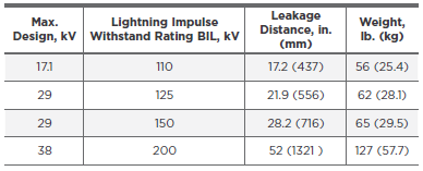
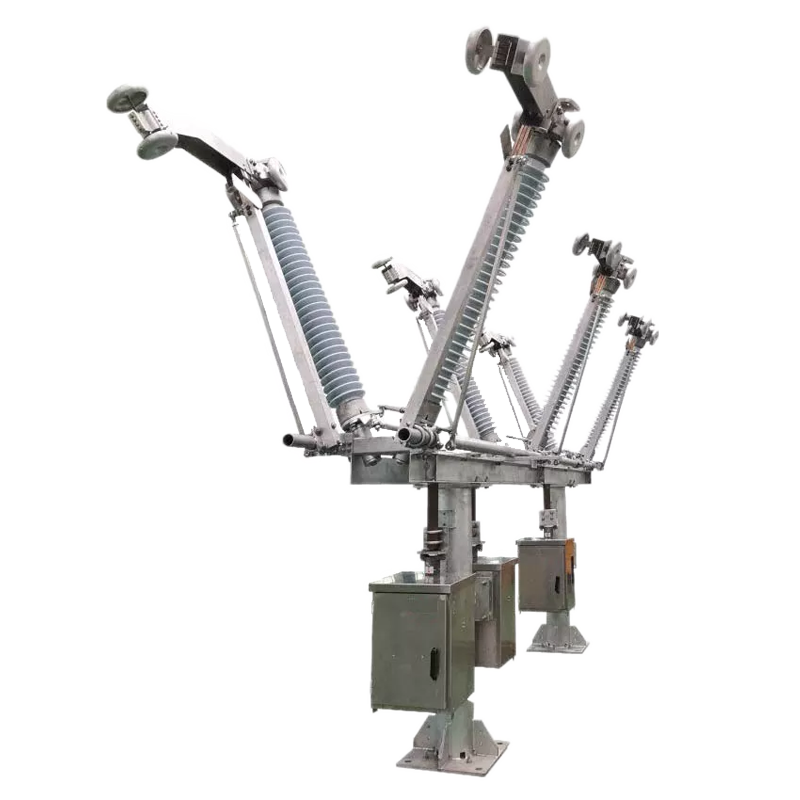
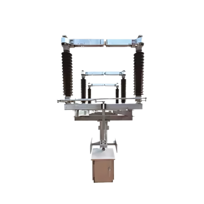
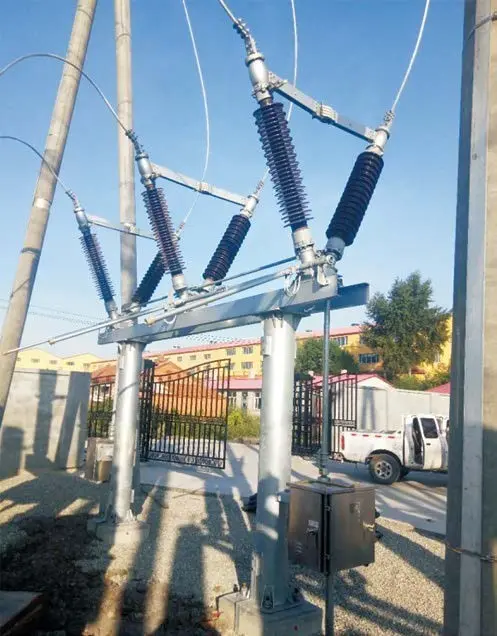
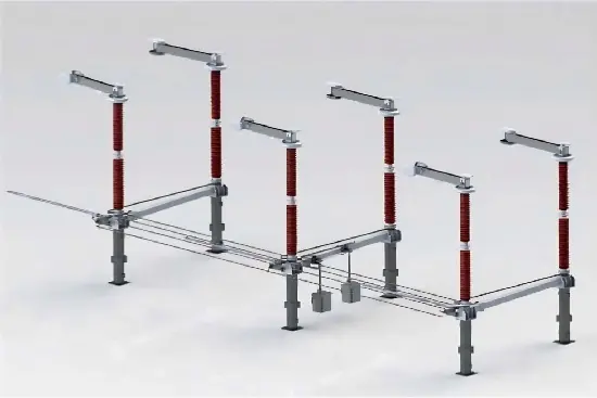
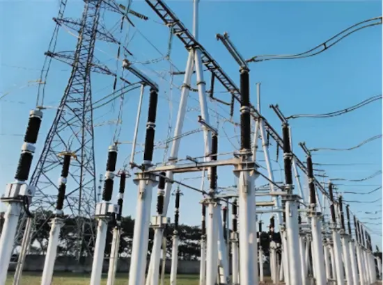
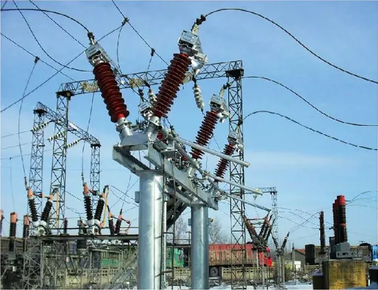
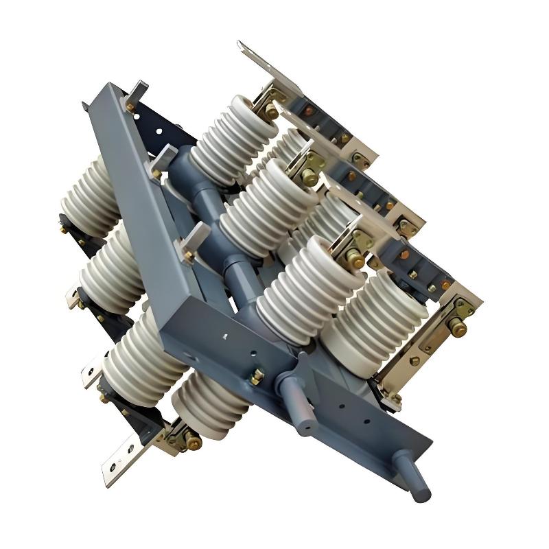
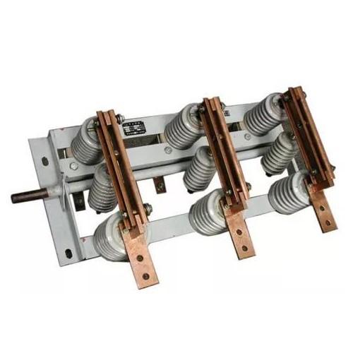
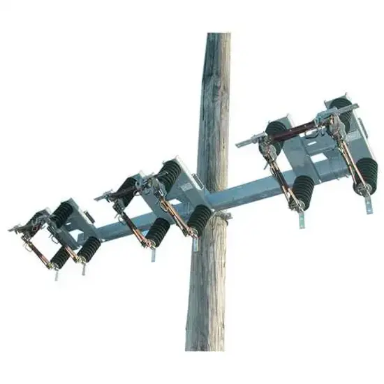
Chance Type BP3 Switches are an economical way to bypass pole mounted distribution reclosers so periodic maintenance can be conducted without interrupting service. The BP3 switches are 3 Pull Operation units that can be offered in either single phase or three phase units. They are rated either 600A or 900A with Voltages Classes of 15, 27 and 38kV with Insulation levels 110kV, 125kV or 150kV BIL. By operating the blades in proper sequence, the recloser is bypassed and isolated from the distribution system. They can be mounted on Cross Arms or directly to the pole via the Pole Mount Bracket Option. They can be configured for either Right Hand or Left Hand opening and either Angled or Non Angled Bypass Blades. Type BP3 switches are not to be used to isolate Voltage Regulators as they have no way to effectively interrupt the circulating current in the regulator windings. Chance: The Brand and Quality You Can Trust!!
Fully Compliant with ANSI/IEEE C37.30.1
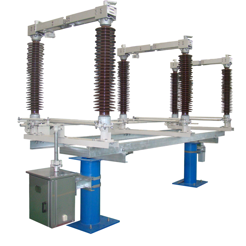
15, 27 and 38kV ratings
110, 125 and 150kV BIL ratings
600A and 900A ratings
ESP Polymer 2.25” Bolt Circle Insulator Assemblies
Right Hand and Left Hand opening Options
Non-Angled and Angled Bypass Blade Options
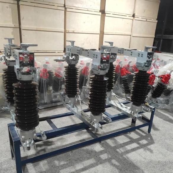
Cross arm or Pole Mount Options
3 Phase on 100” or 124” Cross Arms in Steel or Fiberglass
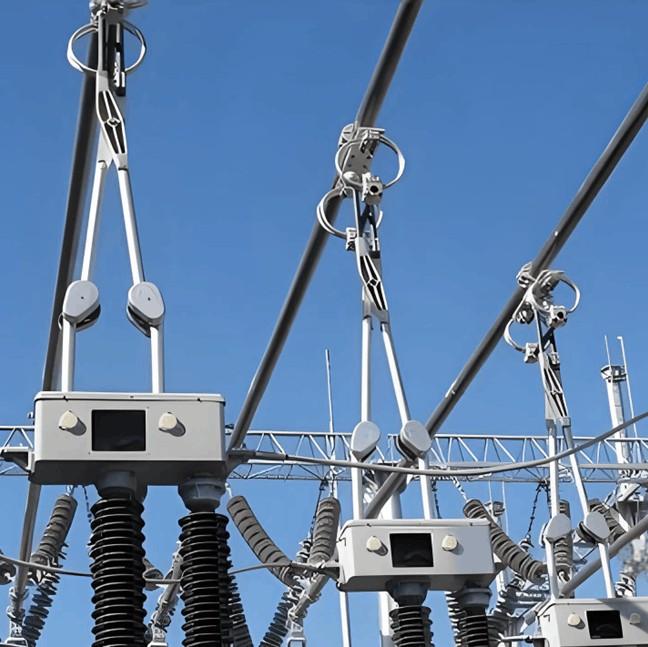
Principal Application: Recloser Maintenance
By design, the BP3 Switch provides an economical means for bypassing and disconnecting a pole-mounted distribution recloser. This permits de-energized periodic maintenance of the recloser without interrupting service. The BP3 Switch accomplishes this by a combination of three disconnect switches mounted on a common base. By operating the blades in proper sequence, the recloser is bypassed and isolated from the distribution system.
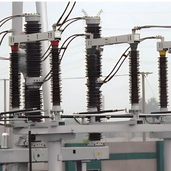
Operation
Figures below illustrate the BP3 Bypass Switch operation. In normal operation, the bypass switchblade is open and the two disconnect blades are closed, allowing the recloser to be in the circuit.
When recloser maintenance, testing, repair or removal isrequired, first close the bypass blade to provide a parallel current path. Then open the recloser’s internal contacts. And last, open both disconnect blades of the bypass switch. In this way, service continuity is maintained and the recloser is isolated from the line. To put the recloser back in service, the switch operating procedure is reversed.
Parameters