• Product
  • Suppliers
  • Manufacturers
  • Solutions
  • Free tools
  • Knowledges
  • Experts
  • Communities
Search


Pole fuse switch disconnector for protecting in LV-networks

  • Pole fuse switch disconnector for protecting in LV-networks

Key attributes

Brand Wone Store
Model NO. Pole fuse switch disconnector for protecting in LV-networks
Rated frequency 50/60Hz
Series SZ

Product descriptions from the supplier

Description

Product Introduction

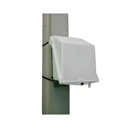
The Pole Fuse Switch Disconnector is a critical protective component designed specifically for low-voltage (LV) networks (typically up to 1kV). Mounted on poles in overhead or vertical distribution setups, it integrates switching, isolation, and fuse-based protection to safeguard LV networks from electrical faults. Its primary role is to interrupt overloads and short circuits, isolate faulty sections, and control power flow—ensuring the stability of residential, commercial, and light industrial LV grids while protecting conductors, transformers, and connected equipment.

Features

  • LV Network-Specific Protection:Optimized for low-voltage environments (≤1kV), it matches the current and voltage demands of LV networks, providing precise protection without over-engineering. Ideal for grids powering homes, offices, and small-scale industrial loads.

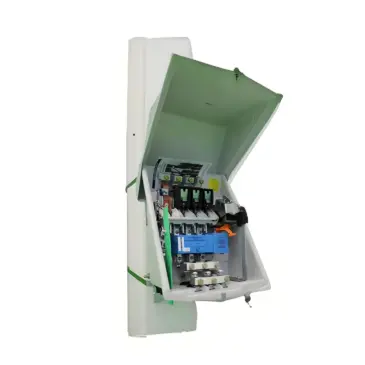
  • Triple Functionality:Combines three key roles: manual switching (to control circuit on/off), safe isolation (for maintenance, preventing electric shock), and fuse-triggered fault interruption (fuses melt to stop overloads/short circuits). Eliminates the need for separate components.

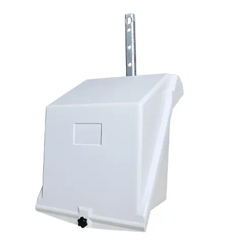
  • Pole-Mounted Design for LV Grid Compatibility:Engineered for pole installation, it fits seamlessly into overhead LV networks—common in suburban and rural areas. The compact, weather-resistant build minimizes space usage while withstanding outdoor conditions (rain, dust, temperature swings).

  • Rapid Fault Response:Fuses react instantly to abnormal currents, interrupting the circuit before damage spreads to other network components (e.g., distribution transformers, consumer meters). This limits downtime and reduces repair costs.

Main Parameters

Certificates

Standards

IEC 60947-3, IEC 60947-1

Dimensions

Weight

9.9 kg

Height

402 mm

Width

319 mm

Length

463 mm

Conductor size Al

50 ... 240 mm²

Electrical values

Nominal insulation voltage

1000 V

Features

Connectors included

6xKG43.6

Number of poles

3

Utilization category

AC22B

ETIM

ETIM Class

EC001040

Max. rated operation voltage Ue AC

500 V

Rated permanent current Iu

400 A

Suitable for fuses

NH2

Number of poles

3

Type of electrical connection of main circuit

Cable clamp

Type of control element

Long turning handle

Know your supplier
Online store
On-time delivery rate
Response time
100.0%
≤4h
Company overview
Workplace: 1000m² Total staff: Highest Annual Export(usD): 300000000
Workplace: 1000m²
Total staff:
Highest Annual Export(usD): 300000000
Services
Business Type: Sales
Main Categories: Wire cable/High Voltage Electrical Apparatus/Low Voltage Electrical Apparatus/Instrument meters/New energy/Tester/Integrated Electrical Equipment/Production equipment/Generator/Electrical fittings/Instrument Transformer/Equipment Parts
Whole life care manager
Whole-life care management services for equipment procurement, use, maintenance, and after-sales, ensuring safe operation of electrical equipment, continuous control, and worry-free electricity consumption.
The equipment supplier has passed platform qualification certification and technical evaluation, ensuring compliance, professionalism, and reliability from the source.

Related Products

Related Knowledges

  • How to Judge, Detect and Troubleshoot Transformer Core Faults
    1. Hazards, Causes, and Types of Multi-Point Grounding Faults in Transformer Cores1.1 Hazards of Multi-Point Grounding Faults in the CoreUnder normal operation, a transformer core must be grounded at only one point. During operation, alternating magnetic fields surround the windings. Due to electromagnetic induction, parasitic capacitances exist between the high-voltage and low-voltage windings, between the low-voltage winding and the core, and between the core and the tank. The energized windin
    01/27/2026
  • A Brief Discussion on the Selection of Grounding Transformers in Boost Stations
    A Brief Discussion on the Selection of Grounding Transformers in Boost StationsThe grounding transformer, commonly referred to as "grounding transformer," operates under the condition of being no-load during normal grid operation and overloaded during short-circuit faults. According to the difference in filling medium, common types can be divided into oil-immersed and dry-type; according to phase number, they can be classified into three-phase and single-phase grounding transformers. The groundi
    01/27/2026
  • Impact of DC Bias in Transformers at Renewable Energy Stations Near UHVDC Grounding Electrodes
    Impact of DC Bias in Transformers at Renewable Energy Stations Near UHVDC Grounding ElectrodesWhen the grounding electrode of an Ultra-High-Voltage Direct Current (UHVDC) transmission system is located close to a renewable energy power station, the return current flowing through the earth can cause a rise in ground potential around the electrode area. This ground potential rise leads to a shift in the neutral-point potential of nearby power transformers, inducing DC bias (or DC offset) in their
    01/15/2026
  • HECI GCB for Generators – Fast SF6 Circuit Breaker
    1.Definition and Function1.1 Role of the Generator Circuit BreakerThe Generator Circuit Breaker (GCB) is a controllable disconnect point located between the generator and the step-up transformer, serving as an interface between the generator and the power grid. Its primary functions include isolating generator-side faults and enabling operational control during generator synchronization and grid connection. The operating principle of a GCB is not significantly different from that of a standard c
    01/06/2026
  • Distribution Equipment Transformer Testing, Inspection, and Maintenance
    1.Transformer Maintenance and Inspection Open the low-voltage (LV) circuit breaker of the transformer under maintenance, remove the control power fuse, and hang a “Do Not Close” warning sign on the switch handle. Open the high-voltage (HV) circuit breaker of the transformer under maintenance, close the grounding switch, fully discharge the transformer, lock the HV switchgear, and hang a “Do Not Close” warning sign on the switch handle. For dry-type transformer maintenance: first clean the porcel
    12/25/2025
  • How to Test Insulation Resistance of Distribution Transformers
    In practical work, insulation resistance of distribution transformers is generally measured twice: the insulation resistance between thehigh-voltage (HV) windingand thelow-voltage (LV) winding plus the transformer tank, and the insulation resistance between theLV windingand theHV winding plus the transformer tank.If both measurements yield acceptable values, it indicates that the insulation among the HV winding, LV winding, and transformer tank is qualified. If either measurement fails, pairwise
    12/25/2025

Related Solutions

  • Dedicated Vacuum Contactor Solution for Port Shore Power Systems
    I. Background and Challenges​Shore power systems have become core technical equipment for ports to reduce carbon emissions and noise pollution. However, these systems face two major challenges in the harsh operational environment of ports:​Severe Environmental Corrosion: High humidity and salt spray in port areas cause serious corrosion to metal components and enclosures of electrical equipment, significantly impacting electrical lifespan and operational reliability.​High Switching Requirements:
    09/13/2025
  • ABB Vacuum Contactor KC2 Power Supply System Technical Transformation Plan
    Issue Overview​The 10kV air compressor starting system of a company utilizes the ABB vacuum contactor KC2 as the control component for the operating circuit. The dedicated wide-voltage power supply module paired with this contactor presents the following issues:​Frequent failures: The power supply module fails to properly transition the voltage from 300V to 12V, resulting in fuse blowouts.​Poor heat dissipation: Enclosed installation of the module leads to insufficient heat dissipation, acceler
    09/13/2025
  • Solution for Medium-Voltage Motor Control and Protection Using Vacuum Contactor-Fuse (VCF) in a Coal Conveying System
    1.Project BackgroundA coal conveying system comprises 15 belt conveyors driven by medium-voltage motors. The system operates under complex conditions, with motors often subjected to heavy loads and frequent starts. To address these challenges and achieve effective control and reliable protection during motor startup, the project comprehensively adopts Vacuum Contactor-Fuse (VCF) combination devices for the 6kV medium-voltage motor power distribution. This solution details the technical features,
    09/13/2025
Haven't found the right supplier yet? Let matching verified suppliers find you. Get Quotation Now
Haven't found the right supplier yet? Let matching verified suppliers find you.
Get Quotation Now
Send inquiry
+86
Click to upload file

IEE Business will not sell or share your personal information.

Download
Get the IEE Business Application
Use the IEE-Business app to find equipment, obtain solutions, connect with experts, and participate in industry collaboration anytime, anywhere—fully supporting the development of your power projects and business.