| Brand | Switchgear parts |
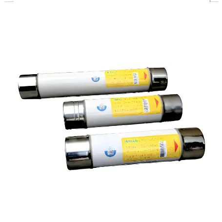
| Model NO. | NH00 fuse linking RT16-00 with double indicator Hrc Ceramic Knife Blade |
| Rated voltage | AC500V |
| Rated normal current | 2-160A |
| Breaking capacity | 120kA |
| Series | RT16-00 NT00 |
The dual indication function refers to two independent fuse indication devices (such as mechanical indicators or visual markers) built into the fuse. When the fuse melts due to overcurrent or overheating, the dual indication mechanism is triggered to intuitively indicate the fault status and improve maintenance efficiency. This type of fuse complies with international standards (such as DIN IEC 60269-1-2) and is suitable for AC voltage systems
Environment
1) Temperature range: -5 ℃~+40 ℃
2) Working humidity range: ≤ 50% (at 40 ℃), ≤ 90% (at 20 ℃).
3) Altitude: ≤ 2000m.
Install
The knife shaped contact fuse needs to be installed with a matching base.
Storage
When storing fuse links, they should be protected from erosion by rain and snow, and stored in a well ventilated warehouse with a relative humidity (at 25 ℃) not exceeding 90%, a temperature not exceeding 40 ℃, and not lower than -30 ℃.
Maintenance
1) Regularly clean the dust and check the contact condition of the contact points.
2) During maintenance and inspection, the power supply must be cut off according to safety regulations, and it is not allowed to remove the fuse when it is live.
Model selection |
Rated voltage V |
Size |
Rated current (melt) A |
Scope of segmentation and category of use |
Rated breaking capacity |
RT16-00(NH00)-2A/500V |
AC500V |
00 |
2 |
gG |
120 |
RT16-00(NH00)-4A/500V |
AC500V |
00 |
4 |
gG |
120 |
RT16-00(NH00)-6A/500V |
AC500V |
00 |
6 |
gG |
120 |
RT16-00(NH00)-8A/500V |
AC500V |
00 |
8 |
gG |
120 |
RT16-00(NH00)-10A/500V |
AC500V |
00 |
10 |
gG |
120 |
RT16-00(NH00)-12A/500V |
AC500V |
00 |
12 |
gG |
120 |
RT16-00(NH00)-16A/500V |
AC500V |
00 |
16 |
gG |
120 |
RT16-00(NH00)-20A/500V |
AC500V |
00 |
20 |
gG |
120 |
RT16-00(NH00)-25A/500V |
AC500V |
00 |
25 |
gG |
120 |
RT16-00(NH00)-32A/500V |
AC500V |
00 |
32 |
gG |
120 |
RT16-00(NH00)-40A/500V |
AC500V |
00 |
40 |
gG |
120 |
RT16-00(NH00)-50A/500V |
AC500V |
00 |
50 |
gG |
120 |
RT16-00(NH00)-63A/500V |
AC500V |
00 |
63 |
gG |
120 |
RT16-00(NH00)-80A/500V |
AC500V |
00 |
80 |
gG |
120 |
RT16-00(NH00)-100A/500V |
AC500V |
00 |
100 |
gG |
120 |
RT16-00(NH00)-125A/500V |
AC500V |
00 |
125 |
gG |
120 |
RT16-00(NH00)-160A/500V |
AC500V |
00 |
160 |
gG |
120 |
RT16-00(NH00)-2A/500V |
AC690V |
00 |
2 |
gG |
120 |
RT16-00(NH00)-4A/690V |
AC690V |
00 |
4 |
gG |
50 |
RT16-00(NH00)-6A/690V |
AC690V |
00 |
6 |
gG |
50 |
RT16-00(NH00)-8A/690V |
AC690V |
00 |
8 |
gG |
50 |
RT16-00(NH00)-10A/690V |
AC690V |
00 |
10 |
gG |
50 |
RT16-00(NH00)-12A/690V |
AC690V |
00 |
12 |
gG |
50 |
RT16-00(NH00)-16A/690V |
AC690V |
00 |
16 |
gG |
50 |
RT16-00(NH00)-20A/690V |
AC690V |
00 |
20 |
gG |
50 |
RT16-00(NH00)-25A/690V |
AC690V |
00 |
25 |
gG |
50 |
RT16-00(NH00)-32A/690V |
AC690V |
00 |
32 |
gG |
50 |
RT16-00(NH00)-40A/690V |
AC690V |
00 |
40 |
gG |
50 |
RT16-00(NH00)-50A/690V |
AC690V |
00 |
50 |
gG |
50 |
RT16-00(NH00)-63A/690V |
AC690V |
00 |
63 |
gG |
50 |
RT16-00(NH00)-80A/690V |
AC690V |
00 |
80 |
gG |
50 |
RT16-00(NH00)-100A/690V |
AC690V |
00 |
100 |
gG |
50 |
RT16-00(NH00)-2A/440V |
DC440V |
00 |
2 |
gG |
120 |
RT16-00(NH00)-4A/440V |
DC440V |
00 |
4 |
gG |
100 |
RT16-00(NH00)-6A/440V |
DC440V |
00 |
6 |
gG |
100 |
RT16-00(NH00)-8A/440V |
DC440V |
00 |
8 |
gG |
100 |
RT16-00(NH00)-10A/440V |
DC440V |
00 |
10 |
gG |
100 |
RT16-00(NH00)-12A/440V |
DC440V |
00 |
12 |
gG |
100 |
RT16-00(NH00)-16A/440V |
DC440V |
00 |
16 |
gG |
100 |
RT16-00(NH00)-20A/440V |
DC440V |
00 |
20 |
gG |
100 |
RT16-00(NH00)-25A/440V |
DC440V |
00 |
25 |
gG |
100 |
RT16-00(NH00)-32A/440V |
DC440V |
00 |
32 |
gG |
100 |
RT16-00(NH00)-40A/440V |
DC440V |
00 |
40 |
gG |
100 |
RT16-00(NH00)-50A/440V |
DC440V |
00 |
50 |
gG |
100 |
RT16-00(NH00)-63A/440V |
DC440V |
00 |
63 |
gG |
100 |
RT16-00(NH00)-80A/440V |
DC440V |
00 |
80 |
gG |
100 |
RT16-00(NH00)-100A/440V |
DC440V |
00 |
100 |
gG |
100 |
RT16-00(NH00)-125A/440V |
DC440V |
00 |
125 |
gG |
100 |
RT16-00(NH00)-160A/440V |
DC440V |
00 |
160 |
gG |
100 |