• Product
  • Suppliers
  • Manufacturers
  • Solutions
  • Free tools
  • Knowledges
  • Experts
  • Communities
Search


DS5A 40.5kV 72.5kV 126kV High voltage disconnect switch source supplier

  • DS5A 40.5kV 72.5kV 126kV High voltage disconnect switch source supplier

Key attributes

Brand ROCKWILL
Model NO. DS5A 40.5kV 72.5kV 126kV High voltage disconnect switch source supplier
Rated voltage 126kV
Rated normal current 3150A
Rated frequency 50/60Hz
Rated peak value withstand current 125kA
Rated short-time withstand current 50kA
Series DS5A

Product descriptions from the supplier

Description

Product introduction:

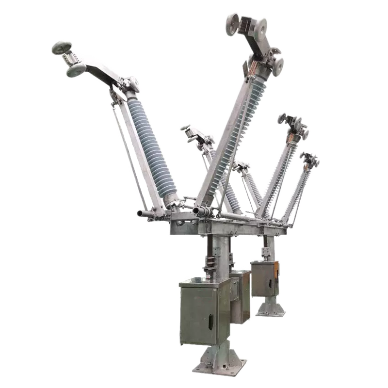
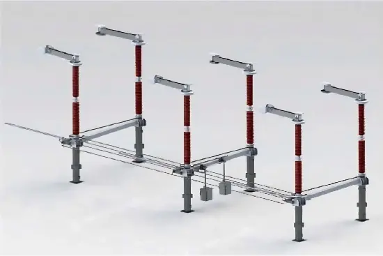
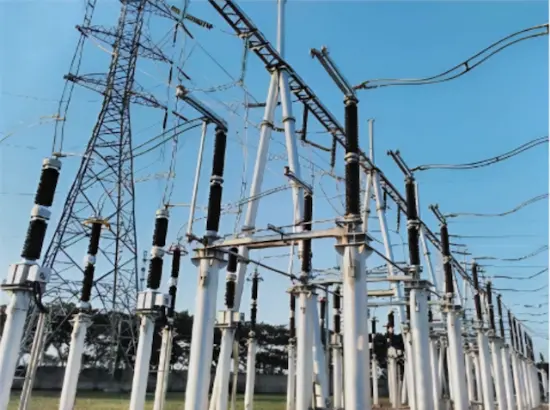
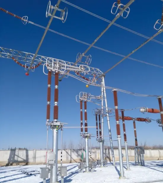
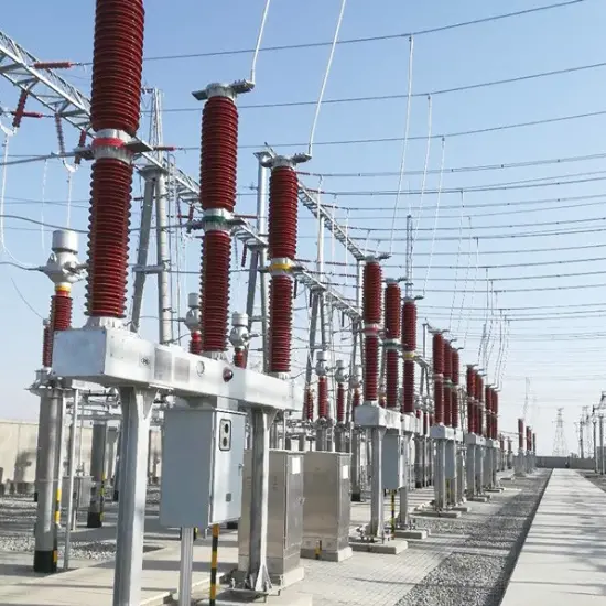
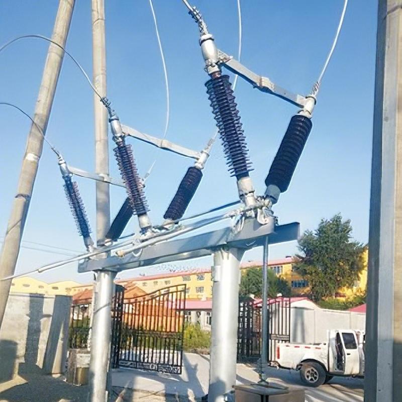
We are China's first source factory specializing in high-voltage disconnectors, boasting advanced technology.The DS5A Switch Disconnector Is a kind of outdoor HV electricity transmission equipment’s at three-phase AC frequency of 50Hz/60Hz. It Is used for breaking or connecting HV lines under no loads so that the power lines can be changed and connected and the way the electricity runs is changed. In addition it can be used to exercise safe eleclrica.1 insulation for such HV electric apparatuses as bus and break.

This product has two posts with horizontal open breaks. It Is open able In the middle and accessible to the grounding switch on one side or two sides. 90° drive's isolating switch and grounding switches adopt cs11 manual operating mechanism to execute the tri-pole linkage;180° drive's isolating switch adopts CS11 manual operating mechanism or CS14g manual to execute the tri-pole linkage; the grounding Switch adopts CS11 manual actuator to realize the tri-pole linkage.

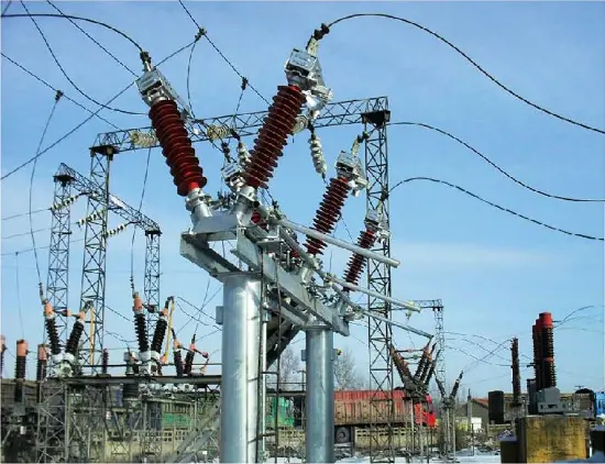
DS5A Switch Disconnector comprises three single poles and actuator. Each single pole is made of a base, post insulator and conductive part. Two rotating post insulators are installed at a base with two insulators forming an angle of 50°; and arranged in V shape. The contact finger arms and contact head arms of the conductive knife switch are separately fixed onto the end of the Insulating post.

The actuator drives one side of the insulating post to revolve, and drives the other side of the insulating post to rotate reversely by 90°; through the angular wheel or link lever, so that the knife switch will be in circumgyration to realize the opening and closing of the Switch Disconnector. A horizontal insulating open break will appear at the closing moment.

Main characteristic:

  • The conductive arm made of rectangular Al-alloy pipes is characterized by high strength, light, weigh, large radiation area and strong resistance against corruption.

  • DS5A adopts particular copper alloy to develop the self-contained contact. The contact point is tightened by the elastic force of the contact itself. The contact spring is eliminated to avoid possible drop of the contact in gripping force due to the spring's corrosion and shunting, possible heating and annealing, possible increment in contact resistance, and possible vicious cycle of the growing heat or the contact The contact is made of curved copper plate, forming a large connection area with the conductive arm. In the opening and dosing processes, there is a short trip of friction between the contact and the finger and the required operating force is small. The conductive part has been acknowledged by the Chinese competent authority as a new and practical patent.(Patent No.: 2103 2 20022.6)

  • The rotating parts of the Switch Disconnector are designed to be free of maintenance. The rotating base is designed into a closure structure which denies the access of moisture, dust and harmful gases so that the low-temperature lubricating cream within the bearing will not run off or harden. Within the bearing base are thrust ball bearing and radial ball bearing, both of which will share the gravity and horizontal component of the Switch Disconnector so that the operating torque will not increase after the long-term operation of the disconnect switch

  • The mechanical interlock between the primary switch and earthing switch is directly installed onto the principal axis of the primary switch and the revolution axis of the earthing switch. The interlock Is direct and reliable, eliminating the structurally complex gearbox. It also facilitates easy adjustment In the field erection and avoids the corrosion of the gear box.

  • Provide one-key sequential control "double confim1ation" function expansion

Main technical parameters:

Specifications

Unit

Value

Model


DS5-40.5

DS5-72.5

DS5-126

Rated voltage

kV

40.5

72.5

126

Rated current

A

2500

2000

2000

Rated frequency

HZ

50

50

50

1min power frequency withstand voltage (r.m.s)

Phase to phase/

to earth

kV

113

230

230

Across isolating distance

kV

118

160(+42)

230(+73)

Lightning impulse withstand voltage (peak 1.2/50us)

Phase to phase/

to earth

kV

185

380

550

Across isolating distance

kV

215

380(+59)

550(+103)

Rated operating impulse withstand voltage(peak 250/2500μs)

Phase to phase/to earth

kV

\

\

\

Across isolating distance

kV

\

\

\

Rated short-time withstand current (r.m.s)

kA

40

40

40

Rated peak withstand time

kA

100

100

100

Rated short-circuit withstand time

S

4

4

3

Wiring terminal static mechanical load

Longitudinal

N

750

750

1000

Horizontal

500

500

750

Vertical

750

750

1000

Operational altitude

m

2000

2000

2000

Operating pollution class

Class

AG5

AG5

AG5

Mechanical life

Times

10K

10K

5K

Radio interference level

uV

500

500

500

bus-transfer current switching by   disconnector

bus-transfer current

A

1600

1600

1600

bus-transfer voltage

V

100

100

100

disconnector switch capacitive open current

A

\

2

1

disconnector switch inductive open current

A

\

1

0.5

The switching induced current capacity of the   earthing switch

Electromagnetic induction current

A

\

\

50

Electromagnetic induction voltage

kV

\

\

0.5

Electrostatic induction current

A

\

\

0.4

Electrostatic induction voltage

kV

\

\

3

Order notice :

Product model, current, rated short-time withstand current and creepage distance must be specified at the goods-ordering time;

The Switch Disconnector offers several options of grounding (no, left, right, both left and right). Unless otherwise specified, the goods suppled will be considered as providing the option of right grounding;

The operating mechanism, voltage and the number of contacts for auxiliary switch;

Methods of installation: horizontal installation, installation by the iodination of 25",side installation. Unless otherwise specified, the horizontal installation will be taken as default;

Specify the type of power and voltage degree for the electromagnetic lock of the actuator.


Documentation Resource Library
Restricted
12 to 800kV Center Vee Center Break Disconnect Switch Installation and Instruction Manuals
Installation Manual
English
Consulting
Consulting
FAQ
Q: What are the key considerations for disconnector selection in high-altitude (>3000m) regions?
A:

Altitude correction is mandatory. Key focus areas include:

  • Increased external insulation distance: ≥15%

  • Derated rated voltage

  • Mechanism anti-condensation design

Recommended Models:

  • Rockwill: DS27-550/5000

  • Pinggao: GW27-550(W)-H

  • Siemens: 3DN3-550 with "High Altitude Kit"

  • Hitachi Energy: DSSP-550 with extended creepage insulators

Know your supplier
Online store
On-time delivery rate
Response time
100.0%
≤4h
Company overview
Workplace: 108000m²m² Total staff: 700+ Highest Annual Export(usD): 150000000
Workplace: 108000m²m²
Total staff: 700+
Highest Annual Export(usD): 150000000
Services
Business Type: Design/Manufacture/Sales
Main Categories: High Voltage Electrical Apparatus/Electric transformer
Whole life care manager
Whole-life care management services for equipment procurement, use, maintenance, and after-sales, ensuring safe operation of electrical equipment, continuous control, and worry-free electricity consumption.
The equipment supplier has passed platform qualification certification and technical evaluation, ensuring compliance, professionalism, and reliability from the source.

Related Products

Related Knowledges

  • Impact of DC Bias in Transformers at Renewable Energy Stations Near UHVDC Grounding Electrodes
    Impact of DC Bias in Transformers at Renewable Energy Stations Near UHVDC Grounding ElectrodesWhen the grounding electrode of an Ultra-High-Voltage Direct Current (UHVDC) transmission system is located close to a renewable energy power station, the return current flowing through the earth can cause a rise in ground potential around the electrode area. This ground potential rise leads to a shift in the neutral-point potential of nearby power transformers, inducing DC bias (or DC offset) in their
    01/15/2026
  • HECI GCB for Generators – Fast SF6 Circuit Breaker
    1.Definition and Function1.1 Role of the Generator Circuit BreakerThe Generator Circuit Breaker (GCB) is a controllable disconnect point located between the generator and the step-up transformer, serving as an interface between the generator and the power grid. Its primary functions include isolating generator-side faults and enabling operational control during generator synchronization and grid connection. The operating principle of a GCB is not significantly different from that of a standard c
    01/06/2026
  • Distribution Equipment Transformer Testing, Inspection, and Maintenance
    1.Transformer Maintenance and Inspection Open the low-voltage (LV) circuit breaker of the transformer under maintenance, remove the control power fuse, and hang a “Do Not Close” warning sign on the switch handle. Open the high-voltage (HV) circuit breaker of the transformer under maintenance, close the grounding switch, fully discharge the transformer, lock the HV switchgear, and hang a “Do Not Close” warning sign on the switch handle. For dry-type transformer maintenance: first clean the porcel
    12/25/2025
  • How to Test Insulation Resistance of Distribution Transformers
    In practical work, insulation resistance of distribution transformers is generally measured twice: the insulation resistance between thehigh-voltage (HV) windingand thelow-voltage (LV) winding plus the transformer tank, and the insulation resistance between theLV windingand theHV winding plus the transformer tank.If both measurements yield acceptable values, it indicates that the insulation among the HV winding, LV winding, and transformer tank is qualified. If either measurement fails, pairwise
    12/25/2025
  • Design Principles for Pole-Mounted Distribution Transformers
    Design Principles for Pole-Mounted Distribution Transformers(1) Location and Layout PrinciplesPole-mounted transformer platforms should be located near the load center or close to critical loads, following the principle of “small capacity, multiple locations” to facilitate equipment replacement and maintenance. For residential power supply, three-phase transformers may be installed nearby based on current demand and future growth projections.(2) Capacity Selection for Three-Phase Pole-Mounted Tr
    12/25/2025
  • Transformer Noise Control Solutions for Different Installations
    1.Noise Mitigation for Ground-Level Independent Transformer RoomsMitigation Strategy:First, conduct a power-off inspection and maintenance of the transformer, including replacing aged insulating oil, checking and tightening all fasteners, and cleaning dust from the unit.Second, reinforce the transformer foundation or install vibration isolation devices—such as rubber pads or spring isolators—selected based on the severity of vibration.Finally, strengthen sound insulation at weak points of the ro
    12/25/2025

Related Solutions

  • Intelligent Operation Solution for 12kV Vacuum Circuit Breakers: Integrating Real-time Monitoring & Lifetime Optimization
    Ⅰ. Equipment Operation & MaintenanceIntelligent Monitoring System Integration​Multi-parameter Real-time Monitoring: Embedded sensors (temperature, displacement, Hall effect current sensors) track contact temperature rise, mechanical characteristics (opening/closing speed, overtravel), coil current, and partial discharge signals. Data undergoes preprocessing via edge computing prior to cloud upload.​Lifetime Prediction Model: Dynamically evaluates remaining lifespan using electrical wear data
    06/10/2025
  • SF6 Circuit Breaker Solutions for Outdoor Installation (Anti-Pollution & Seismic Resistance)
    I.Core Challenges in Outdoor Installation​In high-voltage transmission and distribution systems, SF6 circuit breakers are exposed to complex outdoor environments for extended periods, facing the following critical issues:​Pollution & Insulation Degradation​Dust, salt fog, and industrial pollutants in outdoor environments easily adhere to equipment surfaces. In coastal or industrial areas, pollution levels may reach ​Class IV, resulting in insufficient creepage distance and triggering ​flasho
    05/12/2025
  • 12kV Indoor Vacuum Circuit Breaker Southeast Asia Solution: Anti-Corrosion Compact Design
    12kV Indoor Vacuum Circuit Breaker Southeast Asia Solution: Anti-Corrosion Compact DesignⅠ. Executive Summary​Southeast Asia faces rapidly growing electricity demand alongside environmental challenges including high temperatures, humidity, salt spray corrosion, and grid instability. This solution recommends ​Solid Insulated Pole-Mounted Vacuum Circuit Breakers (VCB)​​ featuring ​high reliability, ​compact design, and ​smart monitoring. Tailored for tropical climates and industrial scenarios, it
    06/10/2025
Haven't found the right supplier yet? Let matching verified suppliers find you. Get Quotation Now
Haven't found the right supplier yet? Let matching verified suppliers find you.
Get Quotation Now
Send inquiry
+86
Click to upload file

IEE Business will not sell or share your personal information.

Download
Get the IEE Business Application
Use the IEE-Business app to find equipment, obtain solutions, connect with experts, and participate in industry collaboration anytime, anywhere—fully supporting the development of your power projects and business.