Electrical Disconnector DNH8(HGL) Series Side Operation – Load Disconnector


Key attributes
| Brand | Switchgear parts |
| Model NO. | Electrical Disconnector DNH8(HGL) Series Side Operation – Load Disconnector |
| Rated normal current | 2000-3150A |
| number of poles | 4p |
| Series | DNH8(HGL) |
Product descriptions from the supplier
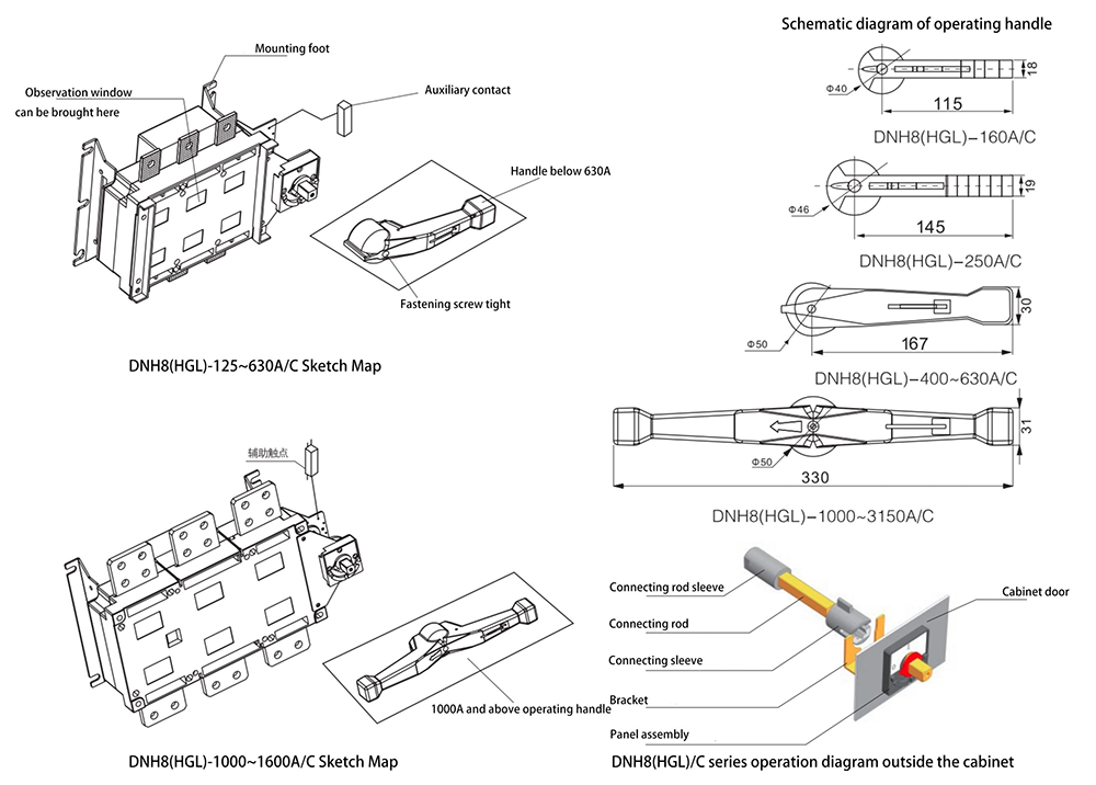
The elastic-accumulating accelerating mechanism for instant release realizes the rapid making and breaking (13.8m/s), having no relation ship with the speed of the operating handle, and increasing greatly the capability of extinguishing electric arc.
The shell made of unsaturated polyester resin reinforced by glass fibre possesses excellent perform ance of flame resistant, dielectric performance, safe operation, resist carbonic performance and resist impact performance.
Parallel double gap contact possesses self cleaning functions.Allthe contact materials are copper alloy plated with silver, and possess two separation contact surfaces.Largeclearance
of insulation.Be on "O" , the products can lock the handle with three locks at the same time and thus can avoid error operation.
Low voltage distribution cabinets that require side layout operation space are commonly used in power distribution systems in industries such as construction and electricity. The specific cabinet body and model details are as follows: GGD fixed low-voltage switchgear, GCK withdrawable low-voltage switchgear, GCS withdrawable low-voltage switchgear, XL-21 power cabinet, etc
Product Details
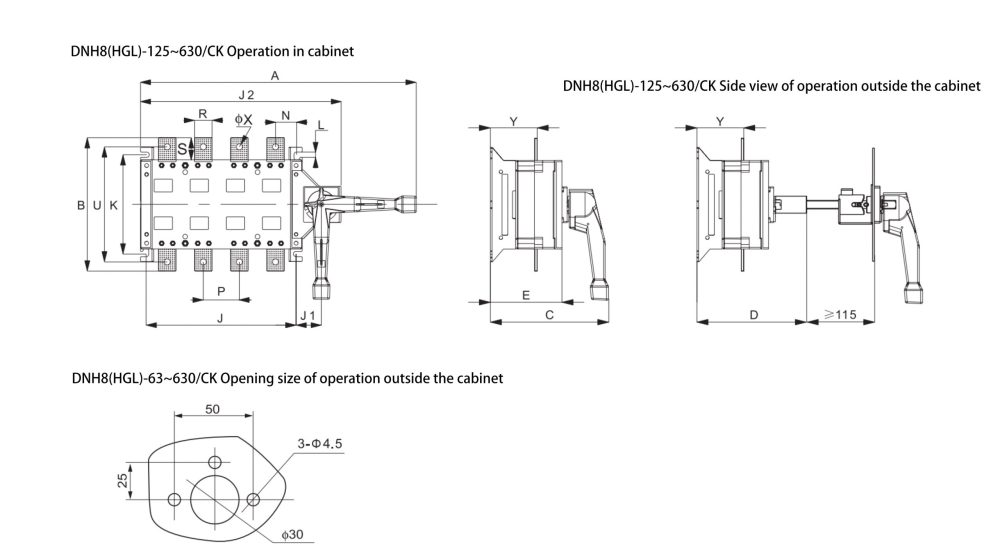
DNH8(HGL)-125~630/C Side Operation Outline and Installation Dimension
Specifications |
Overall dimension | Installation dimension |
|||||||||||||||
| In | A |
B | C | D | E | J1 | J2 | N | P | R | S | U | φX | Y | J | K | L |
| 125A/3 | 273 |
135 | 147 | 156 | 83 | 29 | 195 | 28 | 36 | 20 | 25 | 115 | 9 | 55 | 120 | 95 | 7 |
| 125A/4 | 303 |
135 | 147 | 156 | 83 | 29 | 225 | 22 | 36 | 20 | 25 | 115 | 9 | 55 | 150 | 95 | 7 |
| 160A/3 | 273 |
135 | 147 | 156 | 83 | 29 | 195 | 28 | 36 | 20 | 25 | 115 | 9 | 55 | 120 | 95 | 7 |
| 160A/4 | 303 |
135 | 147 | 156 | 83 | 29 | 225 | 22 | 36 | 20 | 25 | 115 | 9 | 55 | 150 | 95 | 7 |
| 200A/3 | 345 |
170 | 167 | 166 | 95 | 30 | 235 | 33 | 50 | 25 | 30 | 140 | 11 | 64 | 160 | 116 | 9 |
| 200A/4 | 395 |
170 | 167 | 166 | 95 | 30 | 285 | 33 | 50 | 25 | 30 | 140 | 11 | 64 | 210 | 116 | 9 |
| 250A/3 | 345 |
170 | 167 | 166 | 95 | 30 | 235 | 33 | 50 | 25 | 30 | 140 | 11 | 64 | 160 | 116 | 9 |
| 250A/4 | 395 |
170 | 167 | 166 | 95 | 30 | 285 | 33 | 50 | 25 | 30 | 140 | 11 | 64 | 210 | 116 | 9 |
| 315A/3 | 436 |
240 | 213 | 197 | 129 | 45 | 298 | 42 | 50 | 32 | 40 | 206 | 11 | 84 | 270 | 179 | 9.5 |
| 315A/4 | 496 |
240 | 213 | 197 | 129 | 45 | 358 | 38 | 50 | 32 | 40 | 206 | 11 | 84 | 210 | 179 | 9.5 |
| 400A/3 | 436 |
240 | 213 | 197 | 129 | 45 | 298 | 42 | 65 | 32 | 40 | 206 | 11 | 84 | 270 | 179 | 9.5 |
| 400A/4 | 496 |
240 | 213 | 197 | 129 | 45 | 358 | 38 | 65 | 32 | 40 | 206 | 11 | 84 | 210 | 179 | 9.5 |
| 500A/3 | 436 |
260 | 213 | 197 | 129 | 45 | 298 | 42 | 60 | 40 | 50 | 220 | 13 | 84 | 210 | 179 | 9.5 |
| 500A/4 | 496 |
260 | 213 | 197 | 129 | 45 | 358 | 38 | 60 | 40 | 50 | 220 | 13 | 84 | 270 | 179 | 9.5 |
| 630A/3 | 436 |
260 | 213 | 197 | 129 | 45 | 298 | 42 | 60 | 40 | 50 | 220 | 13 | 84 | 210 | 179 | 9.5 |
| 630A/4 | 496 |
260 | 213 | 197 | 129 | 45 | 358 | 38 | 60 | 40 | 50 | 220 | 13 | 84 | 270 | 179 | 9.5 |
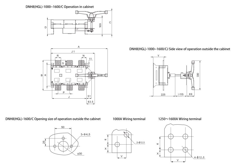
Electrical Disconnector DNH8(HGL)-1000~1600A/C Side Operation Outline and Installation Dimension
isolator switch on or off
Specifications |
Overall dimension | Installation dimension |
|||||||||||||
| In | A |
B | C | D | J1 | N | P | R | S | V | W | X | Y | J | K |
| 1000A/3 | 582 |
308 | 242 | 150 | 450 | 53.5 | 120 | 60 | 55 | 35 | 20 | 16.5 | 109 | 353 | 220 |
| 1000A/4 | 697 |
310 | 242 | 150 | 565 | 50.5 | 120 | 60 | 55 | 35 | 20 | 16.5 | 110 | 471 | 220 |
| 1250A/3 | 582 |
336 | 242 | 150 | 450 | 53.5 | 120 | 80 | 68 | 40 | 35 | 16 | 109 | 353 | 220 |
| 1250A/4 | 697 |
338 | 242 | 150 | 565 | 50.5 | 120 | 80 | 68 | 40 | 35 | 16 | 110 | 471 | 220 |
| 1600A/3 | 582 |
336 | 242 | 150 | 450 | 53.5 | 120 | 80 | 68 | 40 | 35 | 16 | 110 | 353 | 220 |
| 1600A/4 | 697 |
338 | 242 | 150 | 565 | 50.5 | 120 | 80 | 68 | 40 | 35 | 16 | 111 | 471 | 220 |
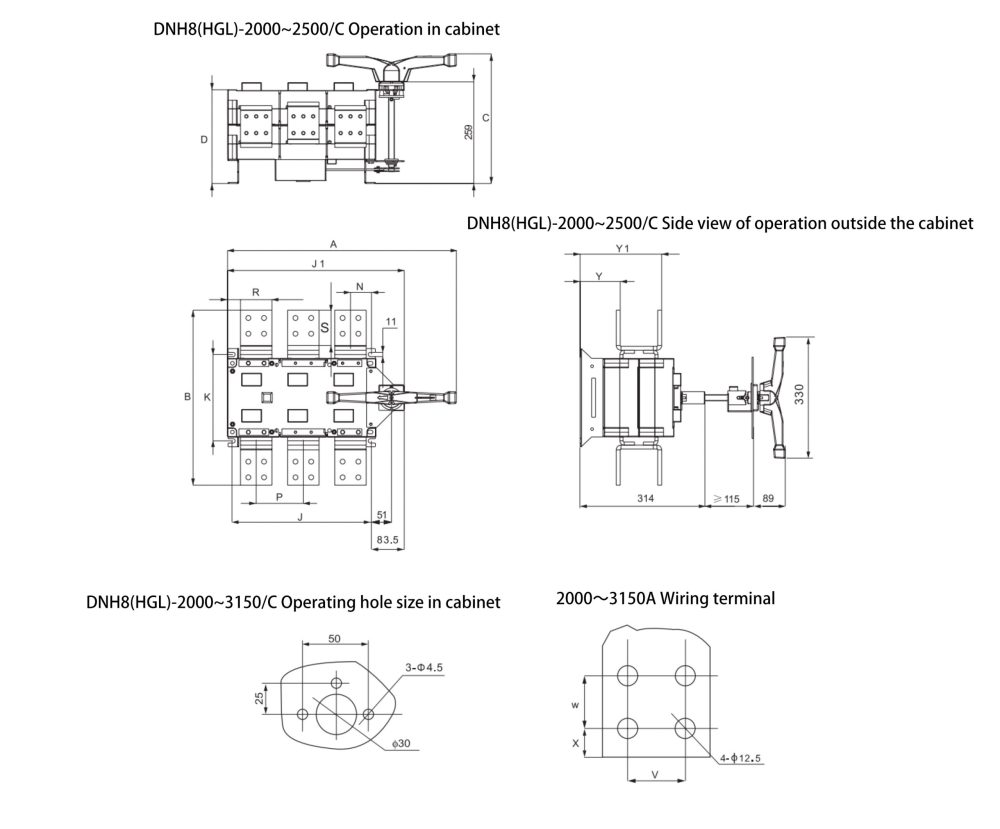
Electrical Disconnector DNH8(HGL)-2000~3150A/C Side operation outline and installation dimension
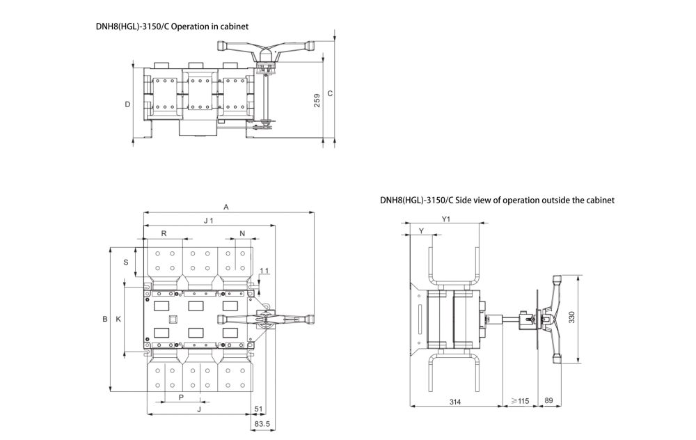
Specifications |
Overall dimension | Installation dimension |
||||||||||||||
| In | A |
B | C | D | J1 | N | P | R | S | V | W | X | Y | Y1 | J | K |
| 2000A/3 | 582 |
445 | 330 | 239 | 450 | 53.5 | 120 | 80 | 90 | 40 | 40 | 20 | 102 | 207.5 | 353 | 220 |
| 2000A/4 | 697 |
447 | 330 | 239 | 565 | 50.5 | 120 | 80 | 90 | 40 | 40 | 20 | 103 | 208.5 | 471 | 220 |
| 2500A/3 | 582 |
445 | 330 | 239 | 450 | 53.5 | 120 | 80 | 90 | 40 | 40 | 20 | 102 | 207.5 | 353 | 220 |
| 2500A/4 | 697 |
447 | 330 | 239 | 565 | 50.5 | 120 | 80 | 90 | 40 | 40 | 20 | 103 | 208.5 | 471 | 220 |
| 3150A/3 | 582 |
492 | 330 | 239 | 450 | 53.5 | 120 | 120 | 101 | 50 | 50 | 21 | 75.5 | 235.5 | 353 | 220 |
| 3150A/4 | 697 |
494 | 330 | 239 | 565 | 50.5 | 120 | 120 | 101 | 50 | 50 | 21 | 76.5 | 236.5 | 471 | 220 |


Related Products
-
160-250A DNH40 Series Disconnector Switch

-
315-400A DNH40 Series Disconnector Switch

-
3200-4000A DNH40 series isolator switches

-
2000-2500A DNH40 Series Disconnector Switch

-
630-800A DNH40 Series Disconnector Switch

-
HH15 series Disconnector fuse group and disconnector

-
Disconnector Fuse Group HGLR Series, Fuse Switch Disconnector

Related Knowledges
-
 Main Transformer Accidents and Light Gas Operation Issues1. Accident Record (March 19, 2019)At 16:13 on March 19, 2019, the monitoring background reported a light gas action of No. 3 main transformer. In accordance with the Code for Operation of Power Transformers (DL/T572-2010), operation and maintenance (O&M) personnel inspected the on-site condition of No. 3 main transformer.On-site confirmation: The WBH non-electrical protection panel of No. 3 main transformer reported a Phase B light gas action of the transformer body, and the reset was ineff02/05/2026
 -
 Faults and Handling of Single-phase Grounding in 10kV Distribution LinesCharacteristics and Detection Devices for Single-Phase Ground Faults1. Characteristics of Single-Phase Ground FaultsCentral Alarm Signals:The warning bell rings, and the indicator lamp labeled “Ground Fault on [X] kV Bus Section [Y]” illuminates. In systems with a Petersen coil (arc suppression coil) grounding the neutral point, the “Petersen Coil Operated” indicator also lights up.Insulation Monitoring Voltmeter Indications:The voltage of the faulted phase decreases (in01/30/2026
 -
 Neutral point grounding operation mode for 110kV~220kV power grid transformersThe arrangement of neutral point grounding operation modes for 110kV~220kV power grid transformers shall meet the insulation withstand requirements of transformer neutral points, and shall also strive to keep the zero-sequence impedance of substations basically unchanged, while ensuring that the zero-sequence comprehensive impedance at any short-circuit point in the system does not exceed three times the positive-sequence comprehensive impedance.For 220kV and 110kV transformers in new constructi01/29/2026
 -
 Why Do Substations Use Stones, Gravel, Pebbles, and Crushed Rock?Why Do Substations Use Stones, Gravel, Pebbles, and Crushed Rock?In substations, equipment such as power and distribution transformers, transmission lines, voltage transformers, current transformers, and disconnect switches all require grounding. Beyond grounding, we will now explore in depth why gravel and crushed stone are commonly used in substations. Though they appear ordinary, these stones play a critical safety and functional role.In substation grounding design—especially when multiple gr01/29/2026
 -
 Why Must a Transformer Core Be Grounded at Only One Point? Isn't Multi-Point Grounding More Reliable?Why Does the Transformer Core Need to Be Grounded?During operation, the transformer core, along with the metal structures, parts, and components that fix the core and windings, are all situated in a strong electric field. Under the influence of this electric field, they acquire a relatively high potential with respect to ground. If the core is not grounded, a potential difference will exist between the core and the grounded clamping structures and tank, which may lead to intermittent discharge.I01/29/2026
 -
 Understanding Transformer Neutral GroundingI. What is a Neutral Point?In transformers and generators, the neutral point is a specific point in the winding where the absolute voltage between this point and each external terminal is equal. In the diagram below, pointOrepresents the neutral point.II. Why Does the Neutral Point Need Grounding?The electrical connection method between the neutral point and earth in a three-phase AC power system is called theneutral grounding method. This grounding method directly affects:The safety, reliabilit01/29/2026


