| Brand | Switchgear parts |
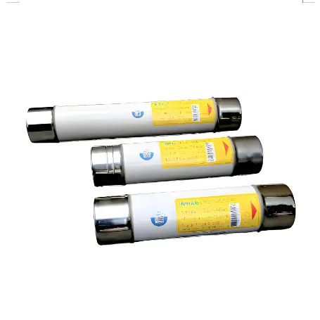
| Model NO. | DNT-J1N Series Semiconductor fuses |
| Rated voltage | AC690V |
| Rated normal current | 800-1600A |
| Breaking capacity | 100kA |
| Series | DNT-J1N |
Semiconductor fuses and standard (or general-purpose) fuses are designed for different applications, and their key differences lie in their operating characteristics and construction.
1.Purpose: Designed specifically to protect sensitive semiconductor devices such as diodes, thyristors, and transistors. These devices can be damaged by overcurrent conditions much more quickly than traditional electrical devices due to their low thermal mass and high heat sensitivity.
2.Operating Speed: Semiconductor fuses are fast-acting fuses that blow very quickly to protect semiconductor devices from even short durations of overcurrent.
3.Current Rating: They have precise current ratings to provide exact protection without a delay that could damage the component they are designed to protect.
4.Energy Let-Through: These fuses have a very low I^2t value, which is the integral of the square of the current over time during the clearing of the fault. This ensures minimal energy let-through and reduces the chance of damage to delicate electronic components.
5.Physical Construction: Semiconductor fuses often use materials and construction methods that allow for the rapid interruption of current. They are generally more compact and may use silver or other high-conductivity materials.
6.Arc Quenching: The construction of semiconductor fuses is such that they are better at quenching the electric arc that occurs when the fuse element melts, due to the materials and the design used.
1.Purpose: Standard fuses are made to protect wiring and prevent fires by interrupting the circuit during prolonged overcurrent conditions. They are used across a wide range of applications, from household electronics to industrial machinery.
2.Operating Speed: They can be fast-acting for some sensitive circuit components, but typically they are slower than semiconductor fuses, allowing for a brief overcurrent condition (like the startup surge of a motor) without blowing.
3.Current Rating: While precise, the current ratings for standard fuses are not as exacting as for semiconductor fuses, because the protected components are not as sensitive to the exact duration and magnitude of overcurrent events.
4.Energy Let-Through: Standard fuses can have a higher I^2t value because the devices they protect can typically withstand more energy without being damaged.
5.Physical Construction: They are often larger and may use different construction materials, as the precision required is not as high. The construction is often focused on durability and longevity rather than quick response.
6.Arc Quenching: While standard fuses also quench arcs, they may not do so as quickly or effectively as semiconductor fuses, because the risk of damage to what they are protecting is not as immediate.
The choice between a semiconductor fuse and a standard fuse depends on the specific requirements of the circuit and the sensitivity of the components involved. It is crucial to select the appropriate type of fuse to ensure both safety and functionality in electrical systems
| Product model | size | Rated voltage V | Rated current A | Rated breaking capacity kA |
| DNT1-JIN-100 | 1 | AC 690 | 100 | 100 |
| DNT1-JIN-125 | 125 | |||
| DNT1-JIN-160 | 160 | |||
| DNT1-JIN-200 | 200 | |||
| DNT1-JIN-250 | 250 | |||
| DNT1-JIN-315 | 315 | |||
| DNT1-JIN-350 | 350 | |||
| DNT1-JIN-400 | 400 | |||
| DNT1-JIN-450 | 450 | |||
| DNT1-JIN-500 | 500 | |||
| DNT1-JIN-550 | 550 | |||
| DNT1-JIN-630 | 630 | |||
| DNT2-J1N-350 | 2 | 350 | ||
| DNT2-J1N-400 | 400 | |||
| DNT2-J1N-450 | 450 | |||
| DNT2-J1N-500 | 500 | |||
| DNT2-J1N-550 | 550 | |||
| DNT2-J1N-630 | 630 | |||
| DNT2-J1N-710 | 710 | |||
| DNT2-J1N-800 | 800 | |||
| DNT2-J1N-900 | 900 | |||
| DNT2-J1N-1000 | 1000 | |||
| DNT2-J1N-1100 | 1100 | |||
| DNT2-J1N-1250 | 1250 | |||
| DNT3-J1N-800 | 3 | 800 | ||
| DNT3-J1N-900 | 900 | |||
| DNT3-J1N-1000 | 1000 | |||
| DNT3-J1N-1100 | 1100 | |||
| DNT3-J1N-1250 | 1250 | |||
| DNT3-J1N-1400 | 1400 | |||
| DNT3-J1N-1500 | 1500 | |||
| DNT3-J1N-1600 | 1600 |