• DNPVF1-32L Fuse holder
  • DNPVF1-32L Fuse holder
DNPVF1-32L Fuse holder
discuss personally
Model
DNPVF1-32L 1500VDC/1P/30kA
Basic info
Brand Switchgear parts
Model NO. DNPVF1-32L Fuse holder
Rated voltage DC 1500V
Rated normal current 32A
number of poles 1P
Breaking capacity 30kA
Series DNPVF1-32L
Product Detail

What is the function of a fuse holder?

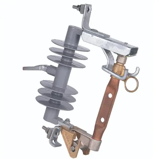
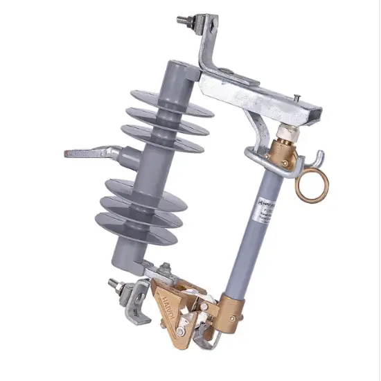
The function of a fuse holder is to provide a secure and easily accessible location for installing and replacing fuses in an electrical circuit. The fuse holder has two primary functions:

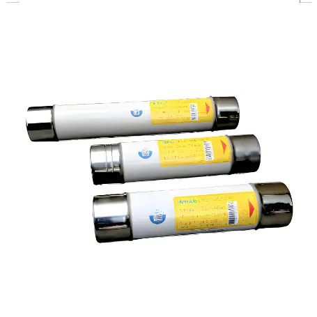
1.Fuse Protection: The main function of a fuse holder is to protect the electrical circuit from excessive current flow. When the current passing through the circuit exceeds the rated capacity of the fuse, the fuse will melt or blow, interrupting the circuit and preventing damage to the circuit components or wiring. The fuse holder holds the fuse in place and ensures proper electrical contact between the fuse and the circuit.

2.Fuse Replacement: Fuse holders allow for easy replacement of fuses when they blow or when maintenance or troubleshooting is required. The holder provides a convenient and safe way to remove the blown fuse and install a new one, minimizing downtime and ensuring the circuit’s protection is restored promptly.

By securely holding the fuse in place and facilitating easy replacement, the fuse holder plays a crucial role in maintaining the safety and functionality of electrical circuits. It helps prevent overloads, short circuits, and potential damage to equipment or wiring, thus safeguarding against electrical hazards and ensuring reliable operation.

Here’s some additional information about the function of a fuse holder:

1.Electrical Contact: Fuse holders ensure proper electrical contact between the fuse and the circuit. They feature terminals or connectors that securely hold the fuse in place while providing a reliable electrical connection. This connection is crucial for the flow of electrical current through the circuit and ensures that the fuse can detect and respond to overcurrent conditions effectively.

2.Mechanical Protection: Fuse holders offer mechanical protection to the fuse. They help prevent accidental contact with the fuse, which could lead to safety hazards or damage to the fuse itself. The holder’s design typically includes features such as covers, enclosures, or shields that protect the fuse from physical impact, dust, moisture, and other environmental factors.

3.Mounting and Installation: Fuse holders come in various configurations to accommodate different mounting requirements. They may be designed for PCB mounting, panel mounting, or in-line installation. The holder’s design allows for secure attachment to the appropriate location, ensuring that the fuse remains in place during operation and minimizing the risk of loose connections or disruptions to the circuit.

4.Fuse Identification: Some fuse holders include labeling or marking features to identify the fuse type, rating, or application. This helps users easily identify the correct replacement fuse and ensures that the circuit is adequately protected. Proper identification of fuses is especially important in applications with multiple fuses or complex electrical systems.

5.Design Flexibility: Fuse holders are available in a wide range of sizes, form factors, and materials to accommodate various fuse types, current ratings, and environmental conditions. This design flexibility allows for compatibility with different applications, enabling users to select the appropriate fuse holder that meets their specific requirements.

Overall, fuse holders provide a crucial role in electrical circuits by protecting against overcurrent conditions, facilitating fuse replacement, ensuring electrical contact, offering mechanical protection, aiding in identification, and providing design flexibility. They are an essential component for maintaining electrical safety and reliability in a wide range of applications, including automotive, industrial, residential, and commercial systems.

Proudct model

DNPVF1-32L

Description

Photovoltaic fuse holder

Pole

1P

Mounting Method

Din rail installation

Wiring range

0.75-25mm²

Fuse Size

10*85mm/14*85mm

Rated operational current le

32A

Rated operational voltage Ue

DC1500V

Rated insulation voltage Ui

DC1500V

Rated impulse withstand current Ipk

8kV

Breaking Capacity with fuse

30kA

Utilization Category

DC-PV0

IP

IP20

Reference Standard

IEC 60947-3 GB/T 14048.3

Know your supplier
Switchgear parts
VoltEdge Solutions​​ specializes in manufacturing premium ​​MV switchgear accessories​​ for global power distribution systems. Our product range includes circuit breaker modules, disconnector spares, and surge arrestors, engineered for ​​24kV+ substations​​ and renewable energy plants. With ISO-certified production and 24/7 technical support, we ensure ​​reliability, compliance​​ with IEC standards, and rapid global supply.
Main Categories
Electrical fittings/Equipment Parts/Low Voltage Electrical Apparatus
Business Type
Sales
Highest Annual Export (USD)
$300000000
Professional Experience
1 years
Workplace
1000m²
占位
占位
Related Products
Related Knowledges
Ensuring Reliability: A Deep Dive into Transformer Maintenance
IntroductionElectric transformers are the backbone of modern power distribution systems, silently enabling the reliable delivery of electricity to homes, businesses, and industries. As these critical assets age and the demand for uninterrupted power grows, the importance of diligent transformer maintenance has never been greater. This essay explores the essential role of transformer maintenance, highlighting the value of proactive care, the impact of advanced diagnostic technologies, and the tra
Vziman
09/03/2025
How does a transformer work?
Transformer Operation PrincipleA transformer is an electrical device that operates on the principle of electromagnetic induction to transfer electrical energy from one circuit to another. It enables the adjustment of voltage levels within an alternating current (AC) system, either stepping up (increasing) or stepping down (decreasing) voltage while maintaining the same frequency.Working Principle:Basic ComponentsA transformer consists of two coils, known as windings—the "primary winding" connect
Rockwell
09/03/2025
Constant testing of high-voltage cable lines
1. Definition of High-Voltage Cable Line Constant TestingHigh-voltage cable line constant testing refers to the systematic measurement, using specialized instruments, of electrical parameters such as resistance, inductance, capacitance, and conductance before a cable line is commissioned or after major maintenance. The aim is to obtain fundamental data characterizing the electromagnetic properties of the cable, serving as a critical testing phase that provides accurate parameter support for powe
Oliver Watts
09/03/2025
Technical Analysis of 220 kV High-Voltage Cable Construction in Winter
1.Work Environment Requirements and Safeguard MeasuresBased on technical requirements for cable equipment storage, laying, transportation, laying, transposition, testing, and cable terminations, the project owner and construction units have conducted extensive trials and implemented protective measures regarding ambient temperature, humidity, bending radius, traction control, and route optimization. These measures ensure high-voltage cable quality and on-site safety under harsh winter conditions
James
09/03/2025
Withstand voltage test of high-voltage cables
Withstand voltage test is an insulation test, but it is a destructive test that can reveal insulation defects difficult to detect in non-destructive testing.The test cycle for high-voltage cables is three years, and it must be conducted after non-destructive tests. In other words, the withstand voltage test is performed only after all non-destructive tests have been passed.Most high-voltage cables used today are cross-linked polyethylene (XLPE) cables, which can have large cross-sections and cov
Oliver Watts
09/03/2025
Analysis of Abnormal Causes of High-Voltage Cable Grounding Circulation and Typical Cases
I. Introduction to Cable Grounding Loop CurrentCables rated 110 kV and above use a single-core structure. The alternating magnetic field generated by the operating current induces a voltage on the metallic sheath. If the sheath forms a closed circuit through the earth, a grounding loop current will flow on the metallic sheath. Excessive grounding loop current (loop current exceeding 50 A, more than 20% of the load current, or a ratio of maximum-to-minimum phase current greater than 3) not only a
Felix Spark
09/03/2025
×
Inquiry
Download
IEE-Business is dedicated to serving the personnel in the global power industry.
Join IEE-Business, not only can you discover power equipment and power knowledge, but also canhnd like - minded friends!